
Subscribe to Our Youtube Channel
Related Manuals for SMW Autoblok LPS 4.0 120 IO


Summary of Contents for SMW Autoblok LPS 4.0 120 IO
- Page 1 COPY OF THE LINEAR POSITION SENSOR ORIGINAL Type LPS 4.0 120 IO Date: 2020-11 Version: Language: English...
-
Page 3: Table Of Contents
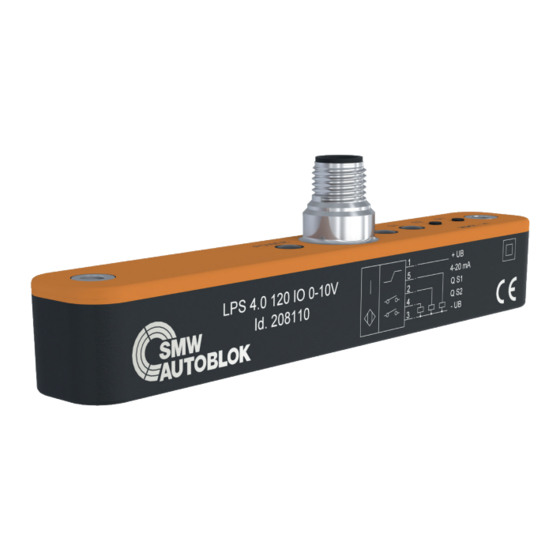
Signal output Mounting Display behavior INSTRUCTION MANUAL IO-Link Process structure and parameters Linear Position Sensor Maintenance Type LPS 4.0 120 IO Troubleshooting with analog interface 0..10V/4..20mA with IO-Link Interface Accessories Measuring range 0..120mm Typeplate Warranty Thank you for purchasing an Original-SMW-AUTOBLOK Linear Position Sensor LPS 4.0. -
Page 4: Declaration Of Incorporation
Product description: Linear Position Sensor Type: LPS 4.0 120 IO Ident-No.: 208109 / 208110 Due to its concept and design as it is introduced into the market is according to the following general safety and health EU regulations. -
Page 5: General Safety Instructions
General safety instructions 1. Intended use 6. General safety advises The linear positioning sensor is exclusively intended • All safety advises, national international to be used as a parts of a production machine. The regulations to avoid accidents as well as company sensor must only be installed and operated by personal internal working and operation advises have to be authorized and advised by the operation, that is qualifi... -
Page 6: Technical Data
C/Q (data) Signal output 0-10 V (Id. No. 208110) Signal output 4-20 mA (Id. No. 208109) Linear position sensor LPS 4.0 120 IO Power supply 24VDC ±10%@ 35mA typ. Inverse-polarity and overvoltage protection Interface 0...10V, short-circuit-proof, oad > 2kOhm (Id. Nr. 208108), 0/4..20mA, load <500 Ohm (Id. -
Page 7: Signal Output
Signal output Analog interface The LPS 4.0 with analog signal output provides 0...10V or 4..20mA, corresponding to 0...48mm. If there is an upper or lower deviation from the measuring range or in case of an error, 0V or 0mA is output. - Page 8 Signal output Analog connection Electric power After the module has been assembled, the cable is connected to When connecting the test sensor to power, all safety advises the PLC control via a shielded connection cable according to the pin of the machine or of the external unit (see the corresponding assignment.
-
Page 9: Mounting
Mounting Mounting LPS 4.0 Special care must be taken when mounting The following procedure is recommended: Special care must be taken when mounting the sensor • Mount the LPS 4.0 by means of a support (not contained in the module since correct mounting is decisive for the quality of •... -
Page 10: Display Behavior
Display behavior Status S3 S2 S1 Standard display behavior of LEDs Color Description Status Green On = supply voltage is OK. Off = no supply voltage Short flashes on and off = IO-Link communication is active Status Flashing (approx. 4 Hz) = a short circuit to a sensor output has been detected Pulsating flashing (approx. -
Page 11: Io-Link Process Structure And Parameters
IO-Link Process Data Structure and Parameters Input data structure Positionswert Function Switching signal 1 Switching signal 2 Switching signal 3 Position value Values bool Switched off Switched n 0... max. position Valid position value in 1/20 mm LPS 4.0 120: 0...2400 4092 Insufficient signal quality 4093... - Page 12 0x04 SMW Autoblok 0x08 IO-Link Vendor ID2 (LSB) uint8 constant 0x46 0x09 Device ID1 (MSB) uint8 constant 0x03 LPS 4.0 120 IO 208108 0-10V 0x0A Device ID2 uint8 constant 0x2C 208107 4-20mA 0x0B Device ID3 (LSB) uint8 constant 0xEC 0-10V...
- Page 13 IO-Link Process Data Structure and Parameters IO-Link Standard Parameters System Command (Index 0x02) Value hex Function 0x82 Restore Factory Settings Profil ID (Index 0x0D) Subindex Value hex Function 0x0001 Smart Sensor Profile supported 0x8000 Device Identification 0x8001 Binary data channel 0x8002 Process Data Variable 0x8003...
- Page 14 IO-Link Process Data Structure and Parameters IO-Link Device Parameter Note: The existing indexes for the various sensors differ according to their properties. For example, indexes for parameterizing an analog out- put are only available for sensors with an analog output. Index Name Data type...
- Page 15 IO-Link Process Data Structure and Parameters Index Name Data type Value Default Unit Switching Signal Channel 3 (Data Storage = yes) 0x4000 Setpoint SP1 unit16 LPS 4.0 120: 0...960 1/20 mm Setpoint SP2 unit16 LPS 4.0 120: 0...960 1/20 mm 0x4001 Switchpoint unit8...
- Page 16 Index Name Data type Value Default Unit Event Configuration (Data Storage = yes) 0x78 No Target bool 0: Disabled (Warning) 1: Enabled Signalfehler bool 0: Disabled 1: Enabled Service Function (Data Storage = no) 0x7F Indication unit8 0: Normal Indication Setting 1: Locator Indication Device Access Locks (Data Storage = yes)
- Page 17 Error Codes In case of a fault, the sensor transmits the error codes detailed in the following table. The error code consists of 2 bytes. The higher value byte, here 0x80, represents the IO-Link device as the emitter. The lower value byte represents the actual fault. Error Error code Comment...
-
Page 18: Maintenance
Maintenance Maintenance, service The LPS 4.0 usually works without maintenance. Any way the function should be tested in regular intervals when testing the machine tool. The following tests need to be carried out: • Check the relative position of the sensor to the cam of the cylinder. •... -
Page 19: Troubleshooting
Handling of errors LPS 4.0 analog The LPS 4.0 sensor is factory set, so that the full measuring range results in a proportional signal of 0-10 Volt or 4-20 mA. In case the sensor detects a non logical position or is out of its measuring range, it will give a 0 Volt or 0 mA output signal. -
Page 20: Accessories
Option Connecting Cable Connection cables and matching connectors are not included in the delivery package. They can be ordered from (special length up to 20m on request). The wire cross section min. 0.34 mm². Description (Connecting Cable for LPS 4.0) SMW-ID-No. -
Page 21: Typeplate
Typeplate Typeplate / Contact For questions on the product and place an order, please indicate the type marked on the label of the sensor type specification and part number. Electrical Connection Sensor Type Id. No. IO Link Label CE Label Measuring Range Contact: SMW-AUTOBLOK Spannsysteme GmbH... - Page 22 Notes SMW-AUTOBLOK...
-
Page 23: Warranty
Warranty 12 month warranty Product: Linear Position Sensor SMW-AUTOBLOK guaranties the proper function of the sensor, if use and storage are in accordance with the technical instructions of this manual. In case the sensor does not perform properly, a repair or exchange is done, after inspecting the circumstances. In case of a production error the sensor is repaired free of charge within the warranty period. - Page 24 SMW-AUTOBLOK...
-
Page 25: Confirmation Of Receipt Of The Manual
Empfangsbestätigung für die Betriebsanleitung Confi rmation of receipt of the instruction manual Hiermit bestätigt die vom Betreiber/ Anwender beauftragte This certifi es the operator assigned by the operating company Person Herr / Frau Mr. / Mrs. den Erhalt der Betriebsanleitung sowie deren Inhalte, hereby confi rms to have received the instruction manual insbesondere das Kapitel Sicherheit gelesen und verstanden and to have read and understood the content, especially the... - Page 27 Id. No. Item Weight Serialno.
- Page 28 SMW-AUTOBLOK s.r.o. Merhautova 20 Turkey CZ - 613 00 Brno SMW AUTOBLOK Makina San, Ve Tic. Ltd. ti. Tel. +420 513 034 157 Yeni ehir Mah, Osmanli Blv, Volume Kurtkoy Ofi s Fax +420 513 034 158 No:9, Kat:1, D:4, 32912, Pendik Istanbul E-mail ...
Need help?
Do you have a question about the LPS 4.0 120 IO and is the answer not in the manual?
Questions and answers