Table of Contents
Advertisement
Quick Links
Hands-free VoIP WiFi Telephone
Confidentiality Notice .....................................................................................................................3
Product Overview ............................................................................................................................3
Features and Functions .......................................................................................................................... 3
System Requirements and Limitations ................................................................................................. 4
VoIP Subscriber Tips ............................................................................................................................. 5
Operation .........................................................................................................................................5
Autodial Emergency Calls ...................................................................................................................... 5
Autodial Non-Emergency Calls ............................................................................................................. 5
General Telephone Calls ........................................................................................................................ 6
Receive a Call .......................................................................................................................................... 6
Multicast Broadcast Reception .............................................................................................................. 6
Installation ......................................................................................................................................6
General Information ............................................................................................................................... 6
Safety Guidelines .................................................................................................................................. 7
Station Placement .................................................................................................................................. 7
Security Hardware ................................................................................................................................ 7
Conduit Installation (Surface-Mount Models) ..................................................................................... 8
Models 393-810A, 393AL-810A, and 394AL-812A (Surface Mount Applications) .......................... 9
Model 397-81xA and 398-81xA Telephones (Flush-Mount Applications) ....................................... 11
Field Wiring ........................................................................................................................................... 14
Recommended Cable .......................................................................................................................... 15
Power .................................................................................................................................................. 16
Network............................................................................................................................................... 16
Antenna ............................................................................................................................................... 16
Auxiliary I/O ....................................................................................................................................... 16
Programming ................................................................................................................................17
First Time WiFi Interface Setup.......................................................................................................... 17
Reset WiFi Interface Configuration .................................................................................................... 20
VoIP Telephone Setup .......................................................................................................................... 20
GAI-TRONICS 3030 KUTZTOWN RD. READING, PA 19605 USA
610-777-1374 ◼ 800-492-1212 ◼ Fax: 610-796-5954
V
ISIT WWW
G A I - T R O N I C S
A H U B B E L L C O M P A N Y
Manual
T
A B L E O F
.
-
.
GAI
TRONICS
COM FOR PRODUCT LITERATURE AND MANUALS
®
C
O N T E N T S
Pub. 42004-545A
Advertisement
Table of Contents

Summary of Contents for REDALERT 393-810A
-
Page 1: Table Of Contents
Station Placement ..........................7 Security Hardware ..........................7 Conduit Installation (Surface-Mount Models) ..................8 Models 393-810A, 393AL-810A, and 394AL-812A (Surface Mount Applications) ......9 Model 397-81xA and 398-81xA Telephones (Flush-Mount Applications) ........11 Field Wiring ............................14 Recommended Cable .......................... 15 Power .............................. - Page 2 Table of Contents Pub. 42004-545A VoIP Telephone Initial Network Configuration ................21 Input Contacts ............................21 Output Contacts ............................ 21 Strobe Connection ..........................21 Monitoring and Reporting ........................22 Maintenance ..........................23 Corrective Actions ..........................23 USB port ..............................23 Troubleshooting ............................ 23 Status Indication ...........................
-
Page 3: Confidentiality Notice
Pub. 42004-545A G A I - T R O N I C S ® A H U B B E L L C O M P A N Y Hands-free VoIP WiFi Telephone Manual Confidentiality Notice This manual is provided solely as an installation, operation, and maintenance guide and contains sensitive business and technical information that is confidential and proprietary to GAI-Tronics. -
Page 4: System Requirements And Limitations
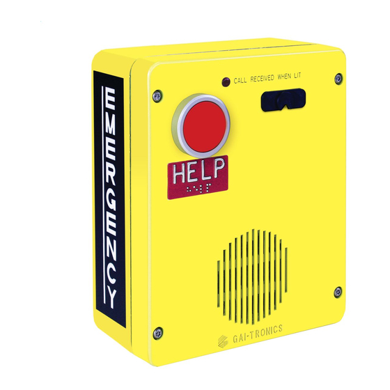
Pub. 42004-545A telephone VoIP WiFi Telephone Manual Page 4 of 29 Table 1. Model Chart Model Description 393-810A Surface-Mount VoIP WiFi Telephone, weatherproof, yellow engineered plastic enclosure, HELP autodial push button, C LED, and 24 V dc ECEIVED power supply. -
Page 5: Voip Subscriber Tips
For questions about interconnected VoIP and 911, or VoIP in general, see http://www.fcc.gov/cgb/consumerfacts/voip.html. Operation Autodial Emergency Calls Models 393-810A, 393AL-810A, 394AL-812A, 397-810A, 397-811A & 398-812A Press the HELP push button to immediately call the preprogrammed emergency number; typically, a security office or 911. •... -
Page 6: General Telephone Calls
Pub. 42004-545A telephone VoIP WiFi Telephone Manual Page 6 of 29 General Telephone Calls Models 394AL-812A, 398-811A, and 398-812A To place a general telephone call: 1. Press the CALL push button. 2. Wait for the dial tone. 3. Use the keypad to dial the desired number. •... -
Page 7: Safety Guidelines
Pub. 42004-545A telephone VoIP WiFi Telephone Manual Page 7 of 29 Safety Guidelines When installing any GAI-Tronics equipment, please adhere to the following guidelines to ensure the safety of all personnel: • Do not install wiring during a lightning storm. •... -
Page 8: Conduit Installation (Surface-Mount Models)
Pub. 42004-545A telephone VoIP WiFi Telephone Manual Page 8 of 29 Conduit Installation (Surface-Mount Models) GAI-Tronics recommends installing power lines in conduit to protect against accidental damage and vandalism. To prevent moisture from entering the enclosure, we strongly recommend the following: •... -
Page 9: Models 393-810A, 393Al-810A, And 394Al-812A (Surface Mount Applications)
When mounting outdoors, installation of a (customer-supplied) surge suppresser on the power line is recommended. Figure 5. Model 393-810A VoIP Telephone in a Non-metallic Enclosure 4. Model 393-810A only: Create a conduit access hole using a hole punch equivalent in size to the conduit diameter. Bottom entry is strongly recommended. - Page 10 VoIP WiFi Telephone Manual Page 10 of 29 Figure 6. Model 393AL-810A Figure 7. Model 394AL-812A Figure 8. Model 393-810A Figure 9. Models 393AL-810A and 394AL-812A Component Locations (Antenna is mounted on back box.) P:\Standard IOMs - Current Release\42004 Instr. Manuals\42004-545A.docx...
-
Page 11: Model 397-81Xa And 398-81Xa Telephones (Flush-Mount Applications)
Pub. 42004-545A telephone VoIP WiFi Telephone Manual Page 11 of 29 Model 397-81 A and 398-81 A Telephones (Flush-Mount Applications) Figure 10. Model 397-810A Figure 11. Model 397-811A 1. Use the supplied back box to mount the Model 397-810A, 397-811A, 398-811A and 398-812A VoIP WiFi telephones in flush-mount applications or in a GAI-Tronics Model 234 Series Communication Station. - Page 12 Pub. 42004-545A telephone VoIP WiFi Telephone Manual Page 12 of 29 Figure 12. Model 398-811A Figure 13. Model 398-812A Figure 14. Component Locations for Models 397-810A, 397-811A, 398-811A, and 398-812A (Shown) P:\Standard IOMs - Current Release\42004 Instr. Manuals\42004-545A.docx 03/20...
- Page 13 Pub. 42004-545A telephone VoIP WiFi Telephone Manual Page 13 of 29 Figure 15. Flush-Mount Telephone Back Box Mounting Detail Panel Cut-Out: 10.13 H × 7.63 W inches (257 × 194 mm) P:\Standard IOMs - Current Release\42004 Instr. Manuals\42004-545A.docx 03/20...
-
Page 14: Field Wiring
Pub. 42004-545A telephone VoIP WiFi Telephone Manual Page 14 of 29 Figure 16. Cutout for Models 397-810A, 397-811A, 398-811A, and 398-812A Field Wiring Pull the required field cables into the rear enclosure and install all connections as indicated in the following subsections (see Table 2 and Figure 17). -
Page 15: Recommended Cable
Pub. 42004-545A telephone VoIP WiFi Telephone Manual Page 15 of 29 Recommended Cable Table 2. Recommended Cable Cable Use Size and Type Power Two-conductor, No. 22 AWG is typical Inputs Two-conductor, No. 22 AWG is typical Output contacts Two-conductor, No. 18 AWG is typical Antenna RG58 coaxial cable Figure 17. -
Page 16: Power
This antenna is pre-connected to the internal antenna connector. • The Model 393-810A uses an internal antenna. • Models 397-81xA and 398-81xA require the use of an external WiFi antenna. The antenna cable must be fed through the rear enclosure of the telephone and secured to the SMA connector. -
Page 17: Programming
Pub. 42004-545A telephone VoIP WiFi Telephone Manual Page 17 of 29 Table 4. Auxiliary Inputs—P12 Label Function Input 4 Common Input 3 Common Input 2 Common Input 1 Common Outputs The telephones have two dry-contact outputs for customer use. Terminate these outputs to connector P10, on the VoIP Carrier PCBA (see Figure 17). - Page 18 Pub. 42004-545A telephone VoIP WiFi Telephone Manual Page 18 of 29 4. Enter admin for both the user and password, and log in. The Working Mode Configuration web page opens: Figure 18. WiFi Interface Working Mode Configuration Web page 5. Select STA M then click the A button.
- Page 19 Pub. 42004-545A telephone VoIP WiFi Telephone Manual Page 19 of 29 Figure 20. WiFi Interface Site Survey Web page 8. Select the desired network and click the A button. PPLY A reminder window to enter the WEP key or pass phrase pops up. 9.
-
Page 20: Reset Wifi Interface Configuration
Pub. 42004-545A telephone VoIP WiFi Telephone Manual Page 20 of 29 12. Click the R button, located in the R section. ESTART ESTART ODULE • … while the WiFi module is restarting. The web page will show R EBOOTING • Both LEDs on the RJ-45 Jack J2 will turn OFF for several seconds while the WiFi interface restarts. -
Page 21: Voip Telephone Initial Network Configuration
Pub. 42004-545A telephone VoIP WiFi Telephone Manual Page 21 of 29 VoIP Telephone Initial Network Configuration Configure each VoIP telephone for operation on the network prior to installation. Assign a local ID, domain, proxy, and registrar. 1. Assign a host name. Host names provide identification of different VoIP PCBAs on the network. -
Page 22: Monitoring And Reporting
Pub. 42004-545A telephone VoIP WiFi Telephone Manual Page 22 of 29 Figure 22. GAI-Tronics Models 540-001/541-001 Strobe Connection Detail Monitoring and Reporting Each telephone recognizes and generates several hardware and configuration fault condition alarms. There are three methods to transmit this information to a remote site: •... -
Page 23: Maintenance
Pub. 42004-545A telephone VoIP WiFi Telephone Manual Page 23 of 29 Maintenance WARNING —This product can contain hazardous voltages. Always remove power to this station prior to servicing. Corrective Actions 1. Inspect and replace frayed or cracked wiring. 2. Secure/replace loose wires and terminal lugs. 3. -
Page 24: Heartbeat
Pub. 42004-545A telephone VoIP WiFi Telephone Manual Page 24 of 29 Heartbeat The HB LED, located on the VoIP PCBA (see Figure 23), flashes when communication over the LAN is established. Link The L LED, located on the VoIP PCBA (see Figure 23), indicates an active network connection when illuminated. -
Page 25: Rload Button
Pub. 42004-545A telephone VoIP WiFi Telephone Manual Page 25 of 29 RLoad Button Press and hold the RL button for 10 seconds to reset the WiFi interface module to the factory default settings. The RL button is located on the WiFi interface module next to the RJ45 jack J2 (see Figure 23). -
Page 26: Cleaning
Pub. 42004-545A telephone VoIP WiFi Telephone Manual Page 26 of 29 Cleaning For general cleaning, wipe the surface with a cleanser or cleanser and water mixture. Any cleanser that is safe for glass is usually safe for stainless steel. Wipe dry. If corrosion or rusting is noticed, remove with a non-abrasive commercial cleanser and water. -
Page 27: Replacement Parts
Pub. 42004-545A telephone VoIP WiFi Telephone Manual Page 27 of 29 Replacement Parts -812A -811A -811A -810A 394AL -812A 393AL -810A -810A P:\Standard IOMs - Current Release\42004 Instr. Manuals\42004-545A.docx 03/20... -
Page 28: Reference Documentation
Relative humidity ....................up to 95%, non-condensing PCBA (printed circuit board assembly) ................conformal coated Model 393-810A Enclosure construction ................engineered plastic, safety yellow Dimensions ............9.50 H × 8.00 W × 4.00 D in (241.3 × 203.2 × 101.6 mm) Weight ............................ -
Page 29: Approvals
Pub. 42004-545A telephone VoIP WiFi Telephone Manual Page 29 of 29 Braille keypad (Model 394AL-812A only) ..............chrome-plated zinc Dimensions ............9.50 H × 8.00 W × 4.00 D in (241.3 × 203.2 × 101.6 mm) Weight: Model 393AL-810A ......................7.8 lb (3.5 kg) Model 394AL-812A ...................... - Page 30 Warranty Equipment. GAI-Tronics warrants for a period of one (1) year from the date of shipment, that any GAI-Tronics equipment supplied hereunder shall be free of defects in material and workmanship, shall comply with the then-current product specifications and product literature, and if applicable, shall be fit for the purpose specified in the agreed upon quotation or proposal document.
Need help?
Do you have a question about the 393-810A and is the answer not in the manual?
Questions and answers