Table of Contents
Advertisement
Quick Links
Advertisement
Table of Contents

Subscribe to Our Youtube Channel
Related Manuals for Atlas LCR40

Summary of Contents for Atlas LCR40
- Page 1 EN40-7 Atlas LCR40 Automatic LCR Meter Model LCR40 (Firmware: 3.72) Designed and manufactured with pride in the UK User Guide © Peak Electronic Design Limited 2002/2021 In the interests of development, information in this guide is subject to change without notice.
-
Page 2: Table Of Contents
Appendix D – Troubleshooting ......... 18 Appendix E – Statutory Information ......... 20 This user guide has been written to accompany the LCR40 meter with revision 3.72 firmware. Other revisions of firmware may differ in operation, features and specifications. The firmware version is displayed briefly upon power-up. -
Page 3: Introduction
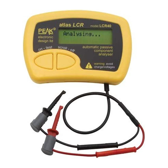
LCR40 User Guide November 2021 – Rev 7 Introduction The Peak Atlas LCR40 is an advanced instrument that greatly simplifies the testing of passive components. Traditional LCR bridges can be inherently complex and very time consuming to use. The LCR40 does everything automatically, it tells you the component type in addition to component value data. -
Page 4: Important Notices
(e.g. charged capacitors). Failure to comply with this warning may result in personal injury, damage to the equipment under test, damage to the LCR40 and invalidation of the manufacturer's warranty. “Analysis of discrete, unconnected components is recommended.”... -
Page 5: Using Your Lcr40
November 2021 – Rev 7 Using your LCR40 Normal Use The LCR40 performs its component analysis before the results are displayed. Therefore, once the analysis has completed, the probes can be disconnected from the component. Analysis itself only takes a few seconds and you can choose to start the analysis after a 5 second delay or immediately. -
Page 6: Probe Compensation
At this point the parasitic and stray characteristics associated with the test leads (and indeed the LCR40 itself) will be stored in non-volatile memory. All further tests will have these values subtracted from the measured values, therefore displaying the characteristics of the component alone. -
Page 7: Testing Inductors
Testing Inductors The LCR40 can analyse most inductors, coils and chokes. Inductor test frequency: The test frequency that the LCR40 uses will be automatically selected from 1kHz, 15kHz or 200kHz. The following table shows the test frequencies used for various inductance ranges:... -
Page 8: Testing Capacitors
LCR40. An electrolytic capacitor can even develop its own stored charge that may be sufficient to cause damage to the LCR40 even after it has been temporarily discharged. This is a characteristic known as dielectric absorption or “Soakage”. - Page 9 Minimum capacitance resolution is about 0.2pF. Capacitor test frequency: The LCR40 uses a high purity sine wave signal of 1kHz, 15kHz or 200kHz to analyse these types of capacitors. The frequency is automatically selected to give the best possible measurement resolution.
- Page 10 LCR40. An electrolytic capacitor can even develop its own stored charge that may be sufficient to cause damage to the LCR40 even after it has been temporarily discharged. This is a characteristic known as dielectric absorption or “Soakage”.
-
Page 11: Testing Resistors
Low Resistance/Inductance Low value inductors (<5µH) and low value resistors (<10Ω) are treated as a special case by the LCR40. This is because low value inductors and low value resistors can exhibit very similar characteristics at the test frequencies available from the LCR40. -
Page 12: Taking Care Of Your Lcr40
1600 operations of 1 minute duration (1 minute is the auto-power-off period). You can improve battery life by switching off the LCR40 before the auto-power-off period expires by pressing and holding the scroll-off button. Page 12... -
Page 13: Self Tests
LCR40 User Guide November 2021 – Rev 7 Self Tests Many internal functions are tested each time the unit is powered up. If any of these self tests do not meet tight Error 02 performance limits, a message will be displayed similar to the following: The unit will then switch off. -
Page 14: Appendix A - Accessories
LCR40 User Guide November 2021 – Rev 7 Appendix A - Accessories A range of useful additions is available to enhance your LCR40. ATC02 – Single Handheld Case A smart handheld case that offers great protection for your instrument as well as space for extra probes and battery. -
Page 15: Appendix B - Component Identification
For example, if the inductance of your component is measured at 100µH and it has a DC resistance of 100Ω, then the LCR40 will tell you that you have a resistor. If however the resistance was only 10Ω, then the LCR40 will tell you that you have an inductor. - Page 16 LCR40 User Guide November 2021 – Rev 7 Capacitor Detection The LCR40 will tell you that you have a capacitor if the following criteria are satisfied: 1. If the measured DC resistance is higher than 10MΩ, even if the measured capacitance is very low (such as open probes).
-
Page 17: Appendix C - Technical Specifications
LCR40 User Guide November 2021 – Rev 7 Appendix C – Technical Specifications All values are at 20C unless otherwise specified. Parameter Note range 1Ω 2MΩ Resistance resolution 0.3 Ω 0.6Ω accuracy Typically ±1.0% ±1.2Ω 1,2,6 range 0.5pF 10,000µF Capacitance resolution 0.2pF... -
Page 18: Appendix D - Troubleshooting
Small variations within the quoted measurement resolutions are normal. Don’t worry, the LCR40 will carry on Calibration date is working after the “Calibration Due Date”. approaching or is in the past. - Page 19 LCR40 User Guide November 2021 – Rev 7 This page is intentionally blank. Appendix E is on the rear cover of this user guide. Page 19...
-
Page 20: Appendix E - Statutory Information
Appendix E – Statutory Information Peak Satisfaction Warranty If for any reason you are not completely satisfied with the LCR40, within 14 days of purchase, you may return the unit to your distributor. You will receive a refund covering the full purchase price if the unit is returned in perfect condition.
Need help?
Do you have a question about the LCR40 and is the answer not in the manual?
Questions and answers