Table of Contents
Advertisement
Quick Links
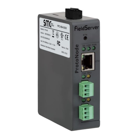
ProtoNode FPC-N54
Start-up Guide
For Interfacing Fulton Products:
Hydronic_ModSync_SE, Hydronic_SOLA_Master, Hydronic_SOLA,
Hydronic_LMV3, Hydronic_LMV3_And_Yokogawa,
Hydronic_LMV3_And_RWF55, Hydronic_LMV5, Hydronic_PURE_Master,
Hydronic_PURE, Steam_ModSync_SE, Steam_LMV3,
Steam_LMV3_And_Yokogawa, Steam_LMV3_And_RWF55, Steam_LMV5
To Building Automation Systems:
BACnet MS/TP, BACnet/IP and SMC Cloud
APPLICABILITY & EFFECTIVITY
Explains ProtoNode hardware and how to install it.
The instructions are effective for the above as of .
Document Revision: 3.A
Web Configurator
Template Revision: 4
Advertisement
Table of Contents

Summary of Contents for FULTON ProtoNode FPC-N54
- Page 1 ProtoNode FPC-N54 Start-up Guide For Interfacing Fulton Products: Hydronic_ModSync_SE, Hydronic_SOLA_Master, Hydronic_SOLA, Hydronic_LMV3, Hydronic_LMV3_And_Yokogawa, Hydronic_LMV3_And_RWF55, Hydronic_LMV5, Hydronic_PURE_Master, Hydronic_PURE, Steam_ModSync_SE, Steam_LMV3, Steam_LMV3_And_Yokogawa, Steam_LMV3_And_RWF55, Steam_LMV5 To Building Automation Systems: BACnet MS/TP, BACnet/IP and SMC Cloud APPLICABILITY & EFFECTIVITY Explains ProtoNode hardware and how to install it.
- Page 2 Thank you for purchasing the ProtoNode for Fulton. Please call Fulton for technical support of the ProtoNode product. Sierra Monitor Corporation does not provide direct support. If Fulton needs to escalate the concern, they will contact Sierra Monitor Corporation for assistance.
- Page 3 Fulton ProtoNode Start-up Guide Quick Start Guide 1. Record the information about the unit. (Section 3.1) 2. Check that the ProtoNode and customer device COM settings match. (Section 3.3) 3. Connect the ProtoNode 3 pin RS-485 R1 port to the RS-485 network connected to each of the devices.
-
Page 4: Table Of Contents
Appendix B.4 Internet Browsers Not Supported ..................43 Appendix B.5 Mounting ........................... 43 Appendix B.6 Physical Dimension Drawing .................... 44 Appendix C Vendor Information – Fulton ....................45 Appendix D Reference ..........................46 Appendix D.1 Specifications ........................46 Appendix D.1.1 Compliance with UL Regulations ................46... - Page 5 Fulton ProtoNode Start-up Guide Appendix E Limited 2 Year Warranty ...................... 47 Page 5 of 47...
- Page 6 Figure 35: Ethernet Port Location ....................... 37 Figure 36: FS-GUI Passwords Page ......................42 Figure 37: Password Recovery Page ......................42 Figure 38: DIN Rail ............................43 Figure 39: ProtoNode FPC-N54 Dimensions ....................44 Figure 40: Specifications ..........................46 Page 6 of 47...
-
Page 7: Certification
Fulton ProtoNode Start-up Guide CERTIFICATION BTL Mark – BACnet ® 1 Testing Laboratory The BTL Mark on ProtoNode is a symbol that indicates that a product has passed a series of rigorous tests conducted by an independent laboratory which verifies that the product correctly implements the BACnet features claimed in the listing. -
Page 8: Introduction
ProtoNode Gateway The ProtoNode is an external, high performance building automation multi-protocol gateway that is preconfigured to automatically communicate between Fulton’s devices (hereafter simply called “device”) connected to the ProtoNode and automatically configures them for BACnet/IP and BACnet MS/TP. It is not necessary to download any configuration files to support the required applications. The ProtoNode is pre-loaded with tested profiles/configurations for the supported devices. -
Page 9: Protonode Setup
Fulton ProtoNode Start-up Guide PROTONODE SETUP Record Identification Data Each ProtoNode has a unique part number located on the side or the back of the unit. This number should be recorded, as it may be required for technical support. The numbers are as follows:... -
Page 10: Configuring Modbus Device Communications
Fulton ProtoNode Start-up Guide Configuring Modbus Device Communications 3.3.1 Confirm the Device and ProtoNode COM Settings Matc h • Any connected serial devices MUST have the same baud rate, data bits, stop bits, and parity settings as the ProtoNode. •... -
Page 11: Interfacing Protonode To Devices
Fulton ProtoNode Start-up Guide INTERFACING PROTONODE TO DEVICES Device Connections to ProtoNode The ProtoNode has a 3-pin Phoenix connector for connecting RS-485 devices on the R1 port. NOTE: Use standard grounding principles for RS-485 GND. ProtoNode Device Pins Pin Label... -
Page 12: Interfacing Protonode To Honeywell Sola Controller
Refer to the boiler Installation and Operation Manual and the electrical drawing for specific wiring requirements. The 24VAC transformer being used to power the SOLA display on Fulton boilers can be used to also power the ProtoNode. Do not wire the 24VAC ground terminal on the ProtoNode. -
Page 13: Interfacing Protonode To Endura+ (Pure) Controller
Fulton ProtoNode Start-up Guide 4.1.3 Interfacing ProtoNode to Endura+ (PURE) Controller There are two profiles available when interfacing with the Endura+ boiler. Hydronic PURE is utilized when all Modbus points are needed for each boiler and Hydronic PURE Master is available for when pulling information from just the Master boiler is sufficient. -
Page 14: Interfacing Protonode To Siemens Lmv3X Controller
Fulton ProtoNode Start-up Guide 4.1.4 Interfacing ProtoNode to Siemens LMV3x Controlle r The LMV3 profile on the ProtoNode shall be selected for boilers where the LMV3x controller installed in them. Refer to the boiler Installation and Operation Manual and the electrical drawing for specific wiring requirements. -
Page 15: Interfacing Protonode To Siemens Lmv5X Control
Fulton ProtoNode Start-up Guide 4.1.5 Interfacing ProtoNode to Siemens LMV5x Control The LMV5 profile on the ProtoNode shall be selected for boilers where the LMV5x controller installed in them. Refer to the boiler Installation and Operation Manual and the electrical drawing for specific wiring requirements. -
Page 16: Interfacing Protonode To Siemens Lmv3X And Yokogawa Controllers
Fulton ProtoNode Start-up Guide 4.1.6 Interfacing ProtoNode to Siemens LMV3x and Yokogawa Controllers The LMV3 and Yokogawa profile will be selected in the ProtoNode for installations containing the Siemens LMV3x and Yokogawa controllers on the boiler. Refer to 4.1.4 above for required LMV3x controller settings. -
Page 17: Interfacing Protonode To Siemens Lmv3X And Rwf55 Controllers
Fulton ProtoNode Start-up Guide 4.1.7 Interfacing ProtoNode to Siemens LMV3x and RWF55 Controllers The LMV3 and RWF55 profile will be selected in the ProtoNode for installations containing the Siemens LMV3x and RWF55 controllers on the boiler. Refer to 4.1.4 above for required LMV3x controller settings. -
Page 18: Wiring Field Port To Rs-485 Serial Network
Fulton ProtoNode Start-up Guide Wiring Field Port to RS-485 Serial Network • Connect the RS-485 network wires to the 3-pin RS-485 connector on the R2 port. (Figure Use standard grounding principles for RS-485 GND • See Section for information on connecting to the Ethernet network. -
Page 19: Bias Resistors
Fulton ProtoNode Start-up Guide Bias Resistors R1 Bias Resistor DIP Switches (2 and 3) R2 Bias Resistor DIP Switches (2 and 3) Figure 11: Bias Resistor DIP Switches To enable Bias Resistors, move both the BIAS- and BIAS+ dip switches to the right in the... -
Page 20: Termination Resistor
Fulton ProtoNode Start-up Guide Termination Resistor R1 Termination Resistor DIP Switch (1) R2 Termination Resistor DIP Switch (1) Figure 12: Termination Resistor DIP Switch If the ProtoNode is the last device on the serial trunk, then the End-Of-Line Termination Switch needs to be enabled. - Page 21 Fulton ProtoNode Start-up Guide Page 21 of 47...
-
Page 22: Power-Up Protonode
Fulton ProtoNode Start-up Guide Power-Up ProtoNode Check power requirements in the table below: Power Requirement for ProtoNode External Gateway Current Draw Type ProtoNode Family 12VDC 24VDC/AC FPC – N54 (Typical) 250mA 125mA NOTE: These values are ‘nominal’ and a safety margin should be added to the power supply of the host system. -
Page 23: Connect The Pc To The Protonode
Fulton ProtoNode Start-up Guide CONNECT THE PC TO THE PROTONODE Connecting to the ProtoNode via Ethernet Connect a Cat-5 Ethernet cable (straight through or cross-over) between the local PC and ProtoNode. Ethernet Port Figure 15: Ethernet Port Location 5.1.1 Changing the Subnet of the Connected PC The default IP Address for the ProtoNode is 192.168.1.24, Subnet Mask is 255.255.255.0. -
Page 24: Configure The Protonode
Fulton ProtoNode Start-up Guide CONFIGURE THE PROTONODE Accessing the ProtoNode Web Configurator • Navigate to the IP Address of the ProtoNode on the local PC by opening a web browser and entering the IP Address of the ProtoNode; the default Ethernet address is 192.168.1.24. -
Page 25: Figure 14: Web App Landing Page
Fulton ProtoNode Start-up Guide • From the Web App landing page (Figure 14), click the Settings tab and then click Configuration. Figure 18: Web App Landing Page • Then click the Profiles Configuration button to go to the Web Configuration page. -
Page 26: Select Field Protocol And Set Configuration Parameters
Fulton ProtoNode Start-up Guide Select Field Protocol and Set Configuration Parameters • On the Web Configurator page, the first configuration parameter is the Protocol Selector. Figure 20: Web Configurator Showing Protocol Selector Parameter • Select the field protocol by entering the appropriate number into the Protocol Selector Value. Click the Submit button. -
Page 27: Set Protonode Active Profiles
Fulton ProtoNode Start-up Guide Set ProtoNode Active Profiles • In the Web Configurator, the Active Profiles are shown below the configuration parameters. The Active Profiles section lists the currently active device profiles, including previous Web Configurator additions. This list is empty for new installations, or after clearing all configurations. -
Page 28: Verify Device Communications
Fulton ProtoNode Start-up Guide • To add an active profile to support a device, click the Add button under the Active Profiles heading. This will present a drop-down menu underneath the Current profile column. (Figure Figure 22: Web Configurator Active Profile Selection •... -
Page 29: Ethernet Network: Setting Ip Address For The Field Network
Fulton ProtoNode Start-up Guide Ethernet Network: Setting IP Address for the Field Network • Follow the steps outlined in Section to access the ProtoAir Web Configurator. • The Web Configurator is displayed as the landing page. (Figure • To access the FS-GUI, click on the “Diagnostics & Debugging” button in the bottom right corner of the page. -
Page 30: Figure 21: Changing Ip Address Via Fs-Gui
Fulton ProtoNode Start-up Guide • From the FS-GUI landing page, click on “Setup” to expand the navigation tree and then select “Network Settings” to access the IP Settings menu. (Figure Figure 25: Changing IP Address via FS-GUI • Modify the IP Address (N1 IP Address field) of the ProtoNode Ethernet port. -
Page 31: How To Start The Installation Over: Clearing Profiles
Fulton ProtoNode Start-up Guide How to Start the Installation Over: Clearing Profiles • Follow the steps outlined in Section to access the ProtoNode Web Configurator. • At the bottom-left of the page, click the “Clear Profiles and Restart” button. •... -
Page 32: Smc Cloud User Setup, Registration And Login
Fulton ProtoNode Start-up Guide SMC CLOUD USER SETUP, REGISTRATION AND LOGIN See the document “SMC_Cloud_Start-up_Guide” for information on this feature. Page 32 of 47... -
Page 33: Appendix A Troubleshooting
Fulton ProtoNode Start-up Guide Appendix A Troubleshooting Appendix A.1 Lost or Incorrect IP Address • Ensure that FieldServer Toolbox is loaded onto the local PC. Otherwise, download the FieldServer-Toolbox.zip via the Sierra Monitor website’s Software Downloads. • Extract the executable file and complete the installation. -
Page 34: Appendix A.2 Viewing Diagnostic Information
Fulton ProtoNode Start-up Guide Appendix A.2 Viewing Diagnostic Information • Type the IP Address of the ProtoNode into the web browser or use the FieldServer Toolbox to connect to the ProtoNode. • Click on Diagnostics Button, then click on view, and then on connections. -
Page 35: Appendix A.3 Checking Wiring And Settings
Fulton ProtoNode Start-up Guide Appendix A.3 Checking Wiring and Settings • No COMS on Modbus RTU side. If the Tx/Rx LEDs are not flashing rapidly then there is a COM issue. To fix this, check the following: A.4) Visual observations of LEDs on ProtoNode... -
Page 36: Appendix A.4 Led Diagnostics For Communications Between Protonode And Devices
Fulton ProtoNode Start-up Guide Appendix A.4 LED Diagnostics for Communications Between ProtoNode and Devices See the diagram below for ProtoNode FPC-N54 LED Locations. FPC-N54 Diagnostic LEDs Description The SS LED will flash once a second to indicate that the bridge is in operation. -
Page 37: Appendix A.5 Take A Fieldserver Diagnostic Capture
Fulton ProtoNode Start-up Guide Appendix A.5 Take a FieldServer Diagnostic Capture When there is a problem on-site that cannot easily be resolved, perform a diagnostic capture before contacting support so that support can quickly solve the problem. There are two methods for taking diagnostic captures: •... - Page 38 Fulton ProtoNode Start-up Guide • Step 1: Take a Log Click on the diagnose icon of the desired device Ensure “Full Diagnostic” is selected (this is the default) NOTE: If desired, the default capture period can be changed. Page 38 of 47...
- Page 39 Fulton ProtoNode Start-up Guide Click on “Start Diagnostic” Wait for Capture period to finish, then the Diagnostic Test Complete window will appear • Step 2: Send Log Once the Diagnostic test is complete, a .zip file is saved on the PC Choose “Open”...
-
Page 40: Appendix A.5.2 Using Fs-Gui
Fulton ProtoNode Start-up Guide Appendix A.5.2 Using FS-GUI Diagnostic Capture via FS-GUI is only available on FieldServers with a bios updated/released on November 2017 or later. Completing a Diagnostic Capture through the FieldServer allows network connections (such as Ethernet and Wi-Fi) to be captured. -
Page 41: Appendix B Additional Information
Fulton ProtoNode Start-up Guide Appendix B Additional Information Appendix B.1 Updating Firmware To load a new version of the firmware, follow these instructions: 1. Extract and save the new file onto the local PC. 2. Open a web browser and type the IP Address of the FieldServer in the address bar. -
Page 42: Appendix B.2 Securing Protonode With Passwords
Fulton ProtoNode Start-up Guide Appendix B.2 Securing ProtoNode with Passwords Access to the ProtoNode can be restricted by enabling a password on the FS-GUI Passwords page – click Setup and then Passwords in the navigation panel. There are 2 access levels defined by 2 account names: Admin and User. -
Page 43: Appendix B.3 Factory Reset Instructions
Fulton ProtoNode Start-up Guide Appendix B.3 Factory Reset Instructions For instructions on how to reset a FieldServer back to its factory released state, see ENOTE - FieldServer Next Gen Recovery. Appendix B.4 Internet Browsers Not Supported • Internet Explorer 11 and prior versions Appendix B.5 Mounting... -
Page 44: Appendix B.6 Physical Dimension Drawing
Fulton ProtoNode Start-up Guide Appendix B.6 Physical Dimension Drawing Power Port R2 Serial Port R1 Serial Port Figure 33: ProtoNode FPC-N54 Dimensions Page 44 of 47... -
Page 45: Appendix C Vendor Information - Fulton
Appendix C Vendor Information – Fulton See the document “Fulton Vendor Mappings” for the complete point list for all the Fulton devices referenced in this manual. Only the protocols listed as supported for this FieldServer are supported (see Section 2.1). -
Page 46: Appendix D Reference
Fulton ProtoNode Start-up Guide Appendix D Reference Appendix D.1 Specifications ProtoNode FPC-N54 One 3-pin Phoenix connector with: RS-485/RS-232 (Tx+ / Rx- / gnd) One 3-pin Phoenix connector with: RS-485 (Tx+ / Rx- / gnd) Electrical Connections One 3-pin Phoenix connector with: Power port (+ / - / Frame-gnd) - Page 47 Fulton Heating Solutions will not pay any charges unless they were pre-approved, in writing, by the Fulton Heating Solutions Quality Manager. This warranty is exclusive and in lieu of all other warranties, expressed or implied, including but not limited to the implied warranties of merchantability and fitness for a particular purpose.
Need help?
Do you have a question about the ProtoNode FPC-N54 and is the answer not in the manual?
Questions and answers