Lindab UltraLink Monitor FTMU Technical Information
Hide thumbs
Also See for UltraLink Monitor FTMU:
- Technical information (18 pages) ,
- Technical information (20 pages) ,
- Technical information (22 pages)

Related Manuals for Lindab UltraLink Monitor FTMU


Summary of Contents for Lindab UltraLink Monitor FTMU
- Page 1 l inda b | we si mpli fy c onst r uction Monitor LindabUltraLink ® FTMU Technical information...
-
Page 2: Table Of Contents
Content Introduction ....................2 Overview ......................3 Description .....................3 Planning ......................4 Mounting ......................6 Connections ....................6 Power supply ....................8 Display ......................9 Settings ......................9 ID-numbers ....................12 Troubleshooting ................... 12 Technical data ....................13 Airflows ......................13 Maintenance .................... -
Page 3: Overview
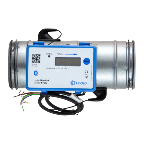
Communication is established via digital signal Monitor FTMU using Modbus. Design The monitor consists of a sensor body with Lindab Safe gaskets. Two flow sensors are mounted on the sensor body and connected to a display unit. The display unit is mounted ontop of a shelf on the sensor body. -
Page 4: Planning
Planning The longer distance to disturbance, i.e. the longer straight duct before the Monitor, the higher the measurement accuracy will be. However this is not the only factor which affects the accuracy of the measurement. The rotation of the Monitor and hence the positioning of the first flow sensor has an impact on the uncertainty of the measurement. - Page 5 Measurement uncertainty ± % or 1 l/s depending wich is the greatest 2-4·Ød >4-5·Ød >5·Ød Disturbance * Placement of first flow sensor Ød Duct diameter Reducer decrease Ød Reducer Duct diameter increase T-piece Inner radius Ød T-piece Outer radius (Not recommended) Ød Ød T-piece...
-
Page 6: Mounting
Mount the Monitor into the air duct system according to the mounting instructions for Lindab Safe. Do not use the flow sensors as handles when you mount the Monitor since this may cause damage and changes in their posi- tions might effect the measurement accuracy. - Page 7 Digital connection Connect A on the RTU to -A on the display unit and B to +B. When connecting more than one Monitor in series it is impor- tant to keep connecting A to A and B to B since crossing them will stop Modbus from working. The shield in the RS485 cable should be continuous over the entire bus, it should ne connected to ground before or at the first UltraLink and at ®...
-
Page 8: Power Supply
Power supply Transformer sizing Power consumption The needed size of 24 V AC transformer(s) can be defined The power consumption for dimensioning supply cables by adding up the dimensioning power consumption [VA] for an UltraLink Monitor is 0,5 VA. ® of all the components. -
Page 9: Display
Display The display can show useful information both with the green diode (status light) and with parameters in the LCD. By short pressing the mode button you can change the displayed parameter. If the button is pressed for more than 5 seconds (long press) then the configuration menu will be visible. - Page 10 Analog output settings #ADDR Name Unit Standard Comment 0 = 0-10 V 1 = 10-0 V Analog Output 1 Level Configuration 4x400 2 = 2-10 V 3 = 10-2 V Display: Analog Output 1 Unit Configuration 0 = Flow 4x401 1 = Temperature Analog Output 1 Temperature Minimum 4x402...
- Page 11 Configuration menu structure The settings that are related to RS485 communication can also be set via the display. The configuration menu is activated by long pressing the button (5 sec). After long pressing the button the first menu option appears in the display. Toggle to the next menu tag by short pressing the button.
-
Page 12: Id-Numbers
Serial no. 132600052 If two or more monitors have the same ID-number it is UltraLink Lindab ® necessary that each of them get an unique ID-number to allow communication. To change the Modbus ID register of an UltraLink ®... -
Page 13: Technical Data
Technical data Power supply AC/DC 24 (18-32) V Cable Max outer diameter 7 mm Power consumption 0,4 W Power consumption For wiring 0,5 VA IP class Sealing class, closed damper Pressure class, closed damper Storage temperature range -30 to +50 °C Maximum ambient moisture 95 % RH Connection... - Page 14 At Lindab, good thinking is a philosophy that gui- des us in everything we do. We have made it our mission to create a healthy indoor climate – and to simplify the construction of sustainable buil- dings. We do that by designing innovative pro- ducts and solutions that are easy to use, as well as offering efficient availability and logistics.
Need help?
Do you have a question about the UltraLink Monitor FTMU and is the answer not in the manual?
Questions and answers