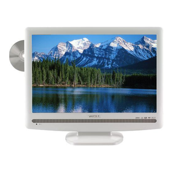
Toshiba 22LV506 Service Manual
22-inch diagonal lcd tv/dvd combination
Hide thumbs
Also See for 22LV506:
- Specifications (2 pages) ,
- Owner's manual (80 pages) ,
- Quick reference manual (8 pages)
Table of Contents
Advertisement
Quick Links
SERVICE MANUAL
22-inch Diagonal LCD TV/DVD
COMBINATION
The above model is classified as a green product (*1), as indicated by the underlined serial number.
This Service Manual describes replacement parts for the green product. When repairing this green
product, use the part(s) described in this manual and lead-free solder (*2).
For (*1) and (*2), see the next page.
©2008 Toshiba Corporation
FILE NO. 810-200875GR
22LV506
DOCUMENT CREATED IN JAPAN, August, 2008 GREEN
Advertisement
Table of Contents

Related Manuals for Toshiba 22LV506


Summary of Contents for Toshiba 22LV506
- Page 1 This Service Manual describes replacement parts for the green product. When repairing this green product, use the part(s) described in this manual and lead-free solder (*2). For (*1) and (*2), see the next page. ©2008 Toshiba Corporation DOCUMENT CREATED IN JAPAN, August, 2008 GREEN...
- Page 2 Hazardous Substances. From July 1, 2006, the RoHS Directive will prohibit any marketing of new products containing the restricted substances. Increasing attention is given to issues related to the global environmental. Toshiba Corporation recognizes environmental protection as a key management tasks, and is doing its utmost to enhance and improve the quality and scope of its environmental activities.
- Page 3 TABLE OF CONTENTS • GREEN PRODUCT PROCUREMENT • LEAD-FREE SOLDER TABLE OF CONTENTS • • OWNER'S MANUAL CAUTION ............................. A1-1 SERVICING NOTICES ON CHECKING ..................A1-2 HOW TO ORDER PARTS ......................A1-2 IMPORTANT SAFEGUARDS ..................... A1-3~A1-5 WHEN REPLACING DVD DECK ....................A1-6 DISC REMOVAL METHOD AT NO POWER SUPPLY ............
- Page 4 - Consult the dealer or an experienced radio/TV technician for help. • The consumer electronics industry SERVICING TO QUALIFIED SERVICE PERSONNEL. CAUTION: Changes or modifications to this equipment not expressly approved by Toshiba could void the user s authority to operate this is committed to making home equipment.
- Page 5 If these sounds become frequent or continuous, Do not use this apparatus near water. store the TV in direct sunlight; hot, humid areas; unplug the power cord and contact a Toshiba Clean only with dry cloth. or areas subject to excessive dust or vibration.
-
Page 6: Table Of Contents
DVD and CD Software and/or the manufacture of DVD and CD discs, Toshiba cannot assure that the DVD player contained in this TV will successfully play every disc bearing the DVD and CD logos. -
Page 7: Antenna Connections
Introduction Identification of controls (Continued) Remote control Inserting batteries The instructions in this manual describe the function on the remote control. See the page in for details. Open the battery compartment Install two “R03/AAA” batteries Replace the compartment cover in the direction of the (supplied), paying attention to cover. -
Page 8: Connecting To Optional Equipment
Your TV/DVD is capable of using ColorStream ® (component video). Connecting your TV/DVD to a component : Signal fl ow Back side (yellow) video compatible DVD player, such as a Toshiba DVD player with ColorStream ® can greatly enhance picture Camcorder (white) quality and performance. -
Page 9: Power Source
Connections Connections Auto Setup Connecting to optional equipment (Continued)/ POWER The Auto Setup function helps to install your TV/DVD easily. Power source It leads you the Language selection, Air/Cable selection and Automatic channel search. IMPORTANT: Make sure that the antenna or cable TV system connection is made! Connecting to a PC (Personal Computer) ENTER... -
Page 10: To Memorize Channels
Basic setup To memorize channels (Continued) ENTER ENTER / / / EXIT/CANCEL EXIT/CANCEL MENU MENU Add/Delete channel Adding Channel Clear All All channels are deleted from the channel memory. You can select the channel that you want to skip. If you find a new channel unregistered, you can add the new channel into the channel memory. -
Page 11: Labeling Channels
TV operation Labeling channels Labeling video inputs Channel label appear with the channel number display each time you turn on the The Video Label feature allows you to label each input source for your TV/DVD. TV/DVD, select a channel, or press DISPLAY. You can choose any four characters to identify a channel. -
Page 12: Setting The Closed Captions
TV operation Setting the V-Chip (continued) As a supplement to the standard V-Chip rating system, your television will 0–9 be able to download an additional rating system, if such a system becomes available in the future. MUTE ENTER ENTER EXIT/CANCEL MENU To set the V-Chip (Continued) To download the additional V-Chip rating system (when available) -
Page 13: Adjusting The Picture Preference
A B C D E F G - - - - - - - - - - - - - - - - - - - - - - - - - - adjust. standard 4:3 with a black side bar. Note: Brightness decrease increase • To select this picture size on 22LV505/22LV506, Picture brightness brightness select “Theater Wide2”. Picture Setting >>... -
Page 14: Sound Control Adjustment
TV operation Sound control adjustment/ Selecting the audio language/ Selecting Stereo/Second Audio Program (SAP) Selecting the HDMI audio input source DISPLAY The multi-channel TV sound (MTS) feature provides high-fidelity stereo sound. When two or more audio languages are included in a digital signal, you can MTS also can transmit a second audio program (SAP) containing a second select one of the audio language. -
Page 15: Basic Playback
Basic playback TV/DVD EJECT Playing a disc POWER POWER EJECT This section shows you the basics on how to play a disc. To obtain a higher quality picture VOLUME + /– Occasionally, some picture noise may appear on the TV screen while playing a DVD video disc because the high resolution pictures on these discs include a + /–... -
Page 16: Marking Desired Scenes
Advanced playback Marking desired scenes Repeat playback/A-B Repeat playback PLAY MODE The unit stores the points that you want to watch again up to 3 points. ENTER You can resume playback from each scene. ENTER PLAY SKIP EXIT/CANCEL REPEAT A-B MARKER Marking the scenes Returning to the scenes... -
Page 17: Changing Soundtrack Language
MP3/WMA and Audio CD playback You must obtain any required permission from copyright owners to download or use copyrighted content. Toshiba cannot and does not grant such permission. Load an Audio CD or a disc on which MP3 About fi le menu Audio CD/MP3/WMA/JPEG/DivX ®... -
Page 18: Repeat, Random And Program Playback Using File Browser
Advanced playback Advanced playback ZOOM ® MP3/WMA/JPEG/DivX and Audio CD DVD MENU ENTER operation (Continued) / / / PAUSE STOP ENTER PLAY SKIP STOP ANGLE PLAY TOP MENU ® JPEG playback Slide show playback DivX ® playback Playing DivX VOD content The slide show enables you to view pictures (fi... -
Page 19: Function Setup
Function setup TV/DVD Customizing the function settings You can change the default settings of the DVD mode to customize performance to your preference. Press TV/DVD on the remote control to select DVD mode. / / / ENTER SETUP RETURN Setting details Setting procedure Section Option... -
Page 20: Temporary Cancel The Rating Level By Dvd Disc
Function setup EJECT Customizing the function settings (Continued) Temporary cancel the rating level by DVD disc 0–9 Depending on the DVD disc, the disc may try to temporarily cancel the rating level that you have set. It is up to you to decide whether to cancel the rating level or not. ENTER RETURN Setting details (continued) -
Page 21: Reception Disturbances
Model 19LV505 / 19LV506 22LV505 / 22LV506 Toshiba America Consumer Products, L.L.C. (“TACP”) makes the following limited warranties to original General consumers in the United States. THESE LIMITED WARRANTIES EXTEND TO THE ORIGINAL CONSUMER PURCHASER OR ANY PERSON RECEIVING THIS LCD TV/DVD COMBINATION AS A GIFT FROM THE... - Page 22 CAUTION THIS LCD COLOR TELEVISION EMPLOYS A LASER SYSTEM. TO ENSURE PROPER USE OF THIS PRODUCT, PLEASE READ THIS SERVICE MANUAL CARE- FULLY AND RETAIN FOR FUTURE REFERENCE. SHOULD THE UNIT REQUIRE MAINTENANCE, CONTACT AN AUTHORIZED SERVICE LOCATION-SEE SERVICE PROCEDURE. USE OF CONTROLS, ADJUSTMENTS OR THE PERFORMANCE OF PROCEDURES OTHER THAN THOSE SPECIFIED HEREIN MAY RESULT IN HAZARDOUS LASER RADIATION EXPOSURE.
- Page 23 SERVICING NOTICES ON CHECKING 1. KEEP THE NOTICES PERFORM A SAFETY CHECK AFTER SERVICING As for the places which need special attentions, they are indicated with the labels or seals on the Confirm that the screws, parts and wiring which cabinet, chassis and parts.
- Page 24 IMPORTANT SAFEGUARDS 1) Read these instructions. 2) Keep these instructions. 3) Heed all warnings. 4) Follow all instructions. 5) Do not use this apparatus near water. 6) Clean only with dry cloth. 7) Do not block any ventilation openings. Install in accordance with the manufacturer's instructions. 8) Do not install near any heat sources such as radiators, heat registers, stoves, or other apparatus (including amplifiers) that produce heat.
- Page 25 IMPORTANT SAFEGUARDS (CONTINUED) 19) If an outside antenna or cable system is connected to the unit, be sure the antenna or cable system is grounded to provide some protection against voltage surges and built-up static charges, Section 810 of the National Electrical Code, ANSI/NFPA 70, provides information with respect to proper grounding of the mast and supporting structure, grounding of the lead-in wire to an antenna discharge unit, size of grounding conductors, location of antenna discharge unit, connection to grounding electrodes, and requirements for...
- Page 26 IMPORTANT SAFEGUARDS (CONTINUED) 25) Do not allow the product to output distorted sound for an extended period of time. It may cause speaker overheating and fire. 26) When you use the headphones, keep the volume at a moderate level. If you use the headphones continu- ously with high volume sound, it may cause hearing damage.
- Page 27 WHEN REPLACING DVD DECK [ When removing the DVD Deck ] Before removing Pick Up PCB and DVD MT PCB connector, the short circuit the position shown in Fig. 1 using a soldering iron. If you remove the DVD Deck with no soldering, the Laser may be damaged. [ When installing the DVD Deck ] Remove all the soldering on the short circuit position after the connection of Pick Up PCB and DVD MT PCB connector.
- Page 28 DISC REMOVAL METHOD AT NO POWER SUPPLY Remove the Back Cabinet and Angle Deck. (Refer to item 1 of the DISASSEMBLY INSTRUCTIONS.) Slide the Belt Loading toward the arrow direction by hand to release the lock. (Refer to Fig. 1) Take out the Disc from the DVD Deck.
- Page 29 REMOTE CONTROL KEY CODE NEC Format Custom Code : 40-BF H, 44-BB H, 45-BA H, 45-BC H Key Name Custom Code Key Code 1 EJECT 45 BA 2 TV/DVD 45 BC 3 SLEEP 40 BF 4 POWER 40 BF 40 BF 40 BF 40 BF 40 BF...
- Page 30 GENERAL SPECIFICATIONS LCD Size / Visual Size 22.0 inch / 558.00mmV System LCD Type Color TFT LCD Number of Pixels 1680(H) x 1050(V) View Range Left/Right 85/85 degree Up/Down 80/80 degree < Bright Dot Zero Bright Dot Ratio Color System NTSC Speaker 2 Speaker...
- Page 31 GENERAL SPECIFICATIONS Power Power Source 120V, 60Hz Power Consumption at AC 65W at 120V 60Hz at DC Stand by (at AC) 1W at 120V 60Hz Energy Star Per Year -- kWh/Year Protector Power Fuse Safety Circuit IC Protector(Micro Fuse) Regulation Safety UL(UL6500_2nd) Radiation...
- Page 32 GENERAL SPECIFICATIONS G-10 Remote Unit RC-LT Control Glow in Dark Remocon Remocon Format TOSHIBA Format TOSHIBA Custom Code 40-BF h ,44-BB h ,45-BA h ,45-BC h Power Source Voltage(D.C) UM size x pcs UM-4 x 2 pcs Total Keys 49 Keys...
- Page 33 GENERAL SPECIFICATIONS G-11 Features Auto Shut Off Auto Search Power On Memory Comb Filter Game Position Auto Setup(Language/CH Program) Picture Setting(TV) Picture Preference Brightness , Contrast , Color Tint Sharpness Color Temperature Cable Clear Picture Setting(PC) HOR Position , VER Position Phase, Clock Red, Green, Blue Auto Adjust...
- Page 34 GENERAL SPECIFICATIONS PC Monitor Input VGA (640x480) Yes (60Hz) VGA (720x400) Yes (70Hz) WVGA (848x480) SVGA (800x600) Yes (60Hz) XGA (1024x768) Yes (60Hz) WXGA (1280x768) Yes (60Hz) WXGA (1280x720) Yes (60Hz) WXGA (1360x768) Yes (60Hz) SXGA (1280x1024) HDMI Input VGA (640×480) Yes (60Hz) 720×480i (4:3) Yes (60Hz)
- Page 35 GENERAL SPECIFICATIONS G-12 Accessories Owner's Manual Language English w/Guarantee Card Remote Control Unit Rod Antenna Poles Terminal Loop Antenna Terminal U/V Mixer DC Car Cord (Center+) Guarantee Card Warning Sheet Circuit Diagram Antenna Change Plug Service Facility List Important Safeguard Dew/AHC Caution Sheet Quick Set-up Sheet(Spanish) Battery...
- Page 36 GENERAL SPECIFICATIONS Indicator Power/Stand-By Yes (Green / Red) Power Wake Up On Timer Terminals Rear Video Input 1 RCA x 1 Audio Input 1 RCA x 2(L/MONO, R) S - Input 1 Video Input 2 Audio Input 2 S - Input 2 Video Output Audio Output Component Input 1...
- Page 37 DISASSEMBLY INSTRUCTIONS 1. REMOVAL OF MECHANICAL PARTS 1-3: POWER PCB (Refer to Fig. 1-3) AND P.C. BOARDS Remove the Holder PCB in the direction of arrow (A). Disconnect the following connectors: (CD301, CP501 and CP8101). CAUTION Remove the 6 screws (1). Be careful not to remove the FFC cable forcibly, because Remove the Power PCB in the direction of arrow (B).
- Page 38 DISASSEMBLY INSTRUCTIONS 1-5: DVD DECK (Refer to Fig. 1-5) Short circuit the position shown in Fig. 1-5 using a soldering iron. If you remove the DVD Deck with no soldering, the Laser may be damaged. Remove the 4 screws (1). Remove the DVD Deck in the direction of arrow (A).
- Page 39 DISASSEMBLY INSTRUCTIONS 2. REMOVAL OF DVD DECK PARTS Check Hook NOTE Check Hook Check Hook 1. Disassemble only the DVD DECK PARTS parts listed here. Minute adjustments are needed if the disassembly is done. If the repair is needed except listed parts, replace the DVD MECHA ASS'Y.
- Page 40 DISASSEMBLY INSTRUCTIONS NOTE Traverse Ass'y When installing the Rack Feed Ass'y, push both ends to Check Hook align the teeth as shown Fig. 2-2-B. Then install it. In case of the Gear Motor installation, check if the value Check Hook of the Fig.
- Page 41 DISASSEMBLY INSTRUCTIONS REMOVAL AND INSTALLATION OF When IC starts moving back and forth easily after desoldering completely, pickup the corner of the IC using FLAT PACKAGE IC tweezers and remove the IC by moving with the IC desoldering machine. (Refer to Fig. 3-3.) REMOVAL NOTE Put Masking Tape (cotton tape) around the Flat Package...
- Page 42 DISASSEMBLY INSTRUCTIONS INSTALLATION When bridge-soldering between terminals and/or the soldering amount are not enough, resolder using a Thin- Take care of the polarity of new IC and then install the tip Soldering Iron. (Refer to Fig. 3-8.) new IC fitting on the printed circuit pattern. Then solder each lead on the diagonal positions of IC temporarily.
- Page 43 SERVICE MODE LIST This unit is provided with the following SERVICE MODES so you can repair, examine and adjust easily. To enter to the SERVICE MODE function, press and hold both buttons simultaneously on the main unit and on the remote control for more than a the standard time in the appropriate condition.
- Page 44 SERVICING FIXTURES AND TOOLS Ref. No. Part No. Parts Name Remarks JG176 Up-Date Disc JG176 Up-Date Disc Up-Date of the Firmware APJG176139 RE-WRITE FOR DVD FIRMWARE Turn on the power, and set the DVD mode. Confirm that the "No Disc" will be appeared on the screen. Press both VOL.
- Page 45 WHEN REPLACING EEPROM (MEMORY) IC CONFIRMATION OF CHECK SUM, POWER ON TOTAL HOURS AND MICON VERSION Initial total of MEMORY IC, POWER ON total hours and MICON VERSIONcan be checked on the screen. Total hours are displayed in 16 system of notation. NOTE: If you set a factory initialization, the total hours is reset to "0".
- Page 46 ELECTRICAL ADJUSTMENTS 1. ADJUSTMENT PROCEDURE FUNCTION FUNCTION BAK LIGHT MIN R DRIVE(N) Read and perform these adjustments when repairing the R CUT OFF(N) BRIGHTNESS CENT circuits or replacing electrical parts or PCB assemblies. G DRIVE(N) BRIGHTNESS MAX CAUTION G CUT OFF(N) BRIGHTNESS MIN B DRIVE(N) TINT...
- Page 47 ELECTRICAL ADJUSTMENTS 2-2: Confirmation of Fixed Value (Step No.) Please check if the fixed values of each of the adjustment item is set correctly referring below. (TV/AV/GAME/COMPONENT/HDMI/DVD/PC/DTV) GAME COMPONENT HDMI FUNCTION CVBS 480i 480p 720p 1080i 480i 480p 720p 1080i 640*480 720*400 800*600 1024*768 1280*768...
- Page 48 ELECTRICAL ADJUSTMENTS 3. ELECTRICAL ADJUSTMENT PARTS LOCATION GUIDE (WIRING CONNECTION) LCD PANEL DVD MT PCB DVD DECK CP2301 CD2001 CP2302 CP8502 CP2303 CD2301 OPERATION PCB CP2201 CD7005 CP7601 OS7601 REMOCON PCB CD7006 CD3002 CD2804 CP3002 CP2804 J8101 J8104 J501 J301 TU5801 J4302 CP3602 J4301...
- Page 49 TROUBLESHOOTING GUIDE (LCD SECTION) POWER DOES NOT TURN ON Change F501. Is F501 broken? Check IC501 and peripheral Is there voltage at pin circuit. 6 of IC501 21V? Is R510 broken? Change R510. Change Digital PCB.
- Page 50 TROUBLESHOOTING GUIDE THE PICTURE APPEARS, BUT THE AUDIO DOES NOT APPEARS. (AT RF MODE) Connect CD301. Is CD301 connected? Is there signal at pins 1 Change SP301 and SP302. and 4 of CD301? Check IC301 and peripheral Is there signal at pins 2 circuit.
- Page 51 TROUBLESHOOTING GUIDE THE PICTURE DOES NOT APPEAR Is CD7005,CD7006 Does backlight shine? Connected CD7005,CD7006. connected ? Check IC7001 and Is the signal pin 18 peripheral circuit. and 19 of IC7001 ? Is the voltage at pin Check F7001. 20 of IC7001 12V ? Is CD2804 connected? Connected CD2804.
- Page 52 TROUBLESHOOTING GUIDE THE COLOR DOES NOT APPEAR Is setting of color Adjust the color. normal? Is the color signal Receive the color signal. received? Is there color signal Check IC2801 and at IC2801? peripheral circuit. Change DIGITAL PCB.
- Page 53 TROUBLESHOOTING GUIDE (DVD SECTION) DOES NOT DISPLAY DVD PICTURE Does this display Check the disc. logo picture? Check pins 8 and 10 of Is there signal at pins 149 CP8501 and peripheral circuit. and 151 of IC4001? Does IC4001 gets P.CON+3.3V and Change IC4001.
- Page 54 TROUBLESHOOTING GUIDE DISC DOES NOT EJECT Check pins J18 and J19 of Does OSD appear Is remote key set IC2801 and peripheral on the screen? effectively? circuit. Check pins 138 and 139 of IC4001 and peripheral circuit. Check IC4001 and Does this eject disc at Is there signal at pins 4 peripheral circuit.
- Page 55 TROUBLESHOOTING GUIDE DOES NOT PLAY DVD Change DVD DECK. Is the voltage between Does CD2001 connect Does this display JG017 and JG018 less with CP2301 correctly? "INCORRECT DISC"? than 0.6V? Connect CD2301. Does this display Change IC4001. reading mark? Change DVD DECK. Does disc rotate? Change IC4001.
- Page 56 TROUBLESHOOTING GUIDE DOES NOT PLAY CD Change DVD DECK. Is the voltage between Does CD2001 connect Does this display JG019 and JG018 less with CP2301 correctly? "INCORRECT DISC"? than 0.6V? Connect CD2301. Does this display Change IC4001. reading mark? Change DVD DECK. Does disc rotate? Change IC4001.
- Page 57 TROUBLESHOOTING GUIDE NO SOUND DVD/CD ANALOG AUDIO Is there signal at pins 113, 114, 115 and Change IC4001. 116 of IC4001? Check pins 1 and 7 of IC8501 Is there signal at pins 1 and peripheral circuit. and 7 of IC8501? Connected CD8501.
- Page 58 MECHANICAL EXPLODED VIEW 103B 103C PCB270 (OPERATION PCB ASS'Y) 103A 103D 102D 102E 102D 102A 102E PCB130 (DVD MT PCB ASS'Y) 102B PCBDA0 (REMOCON PCB ASS'Y) 102C PCB240 (POWER PCB ASS'Y) PCBDH0 104F (DIGITAL PCB ASS'Y) 104D 104E 104E 104D 104D 101C 104D...
- Page 59 MECHANICAL EXPLODED VIEW (PACKING DIAGRAM) 129, 130, 131, 132, 133, 134, CD501, TM101 J1-3...
- Page 60 DVD DECK EXPLODED VIEW CD2001 M2602 Do not replace the parts. Because, minute adjustments are needed if this condition is disassembled further more. If the repair is needed, replace the DVD MECHA ASS'Y. PCB640 (SW PCB ASS'Y) CD2301 NOTE: Applying positions AA for the grease are displayed for this section. CLASS MARK Check if the correct grease is applied for each position.
- Page 61 ANGLE MPEG AE009590 706KSAA001 HINGE ASS'Y AE009650 706WPA0034 COVER CONNECTOR AE009625 8900P3545B RIVET AE009857 722549A739 SHEET RATING AE009416 723000D607 MERCURY CAUTION LABEL (TOSHIBA) AE009652 723000D807 SHEET JACK-1 AE009653 723000D808 SHEET JACK-2 AE001853 8965TS1017 CUSHION 65TS10-10(17.5*20*14) AE005122 726000A073 SHEET CAUTION AE009597 744WUA0029...
- Page 62 DVD DECK REPLACEMENT PARTS LIST Location No. TSB P/N Reference No. Description ! 600 AE009615 A50N01P650 DVD MECHA ASS'Y A50N01P650 AE008499 92SBB0033A LOADER SUB ASS'Y DLM1D29-31 AE005815 92AAA0017A FEED RACK ASS'Y AE003551 92P100088A GEAR,MOTOR AE005805 92P100117A GEAR,MIDDLE AE008500 92P200017A INSULATOR, F AE008501 92P200018A INSULATOR, R...
- Page 63 ELECTRICAL REPLACEMENT PARTS LIST Location No. TSB P/N Reference No. Description RESISTORS ! R503 75006901 RC31X1126J 12M OHM 1W ! R505 AE009485 R63884330J R,FUSE OHM 1/4W ! R509 AE009486 RC31X1125J 1.2M OHM 1W ! R510 AE005735 R63881R22J R,FUSE 0.22 OHM 1W ! R512 AE009487 R3K781563J...
- Page 64 ELECTRICAL REPLACEMENT PARTS LIST Location No. TSB P/N Reference No. Description DIODES D7015 BZ410006 D1VT001330 DIODE,SILICON 1SS133T-77 D7016 AE009006 DGERMA1110 DIODE SILICON MA111-(TX) D7017 AE009006 DGERMA1110 DIODE SILICON MA111-(TX) D7018 BZ410006 D1VT001330 DIODE,SILICON 1SS133T-77 D7019 AE009006 DGERMA1110 DIODE SILICON MA111-(TX) D7020 AE009006 DGERMA1110...
- Page 65 ELECTRICAL REPLACEMENT PARTS LIST Location No. TSB P/N Reference No. Description TRANSISTORS Q6201 AE009515 T27T030190 2SK3019_TL Q6202 AE009515 T27T030190 2SK3019_TL Q6203 BZ510072 TPAAC05002 COMPOUND TRANSISTOR KRA103SRTK Q6204 BZ510071 TNAAB05003 COMPOUND TRANSISTOR KRC102SRTK Q7003 BZ510113 T27T030180 2SK3018T106 Q7004 AE009516 T250A06J30 TK30A06J3(ORION.Q) Q7005 AE009516 T250A06J30...
- Page 66 ELECTRICAL REPLACEMENT PARTS LIST Location No. TSB P/N Reference No. Description MISCELLANEOUS B3009 AE007761 024AC5181J CORE,BEADS BLM18PG181SN1D B3010 AE007761 024AC5181J CORE,BEADS BLM18PG181SN1D B3011 AE007761 024AC5181J CORE,BEADS BLM18PG181SN1D B3012 AE007761 024AC5181J CORE,BEADS BLM18PG181SN1D B3013 AE007761 024AC5181J CORE,BEADS BLM18PG181SN1D B3014 AE007761 024AC5181J CORE,BEADS BLM18PG181SN1D B3015...
- Page 67 ELECTRICAL REPLACEMENT PARTS LIST Location No. TSB P/N Reference No. Description MISCELLANEOUS NR2811 AE009556 11074220M7 R,NETWORK CRA108220JV NR2812 AE009556 11074220M7 R,NETWORK CRA108220JV NR2813 AE009556 11074220M7 R,NETWORK CRA108220JV NR6551 AE009557 11074470M7 R,NETWORK CRA108470JV OS7601 AE008414 077A033001 REMOTE RECEIVER ROM-V338TAO ! SP301 AE009558 070Y433004 SPEAKER...
- Page 68 TOSHIBA CORPORATION 1-1, SHIBAURA 1-CHOME, MINATO-KU, TOKYO 105-8001, JAPAN...
Need help?
Do you have a question about the 22LV506 and is the answer not in the manual?
Questions and answers