Table of Contents
Advertisement
Quick Links
Low Power 4 way Return Path Optical Receiver
I Product Introductions:
· High quality optical receiver device for photoelectric conversion
· High-performance dynamic noise isolation switch (DNIS optional)
· 5~65 MHz RF bandwidth to meet various CATV system requirements
· High quality low power reverse amplifier module, improves reliability
· Modular design, independent four-channel receiver module, adopts all-metal
shielded housing, greatly increasing isolation between ports.
· RFoG or Normal - two operating modes optional
· High quality switching power supply, wide range and high reliability
· Electric circuit safety (over-voltage, lightning protection)
· Simple LCD display control and network management interface
II Performance Introductions:
1、Structure Characteristics
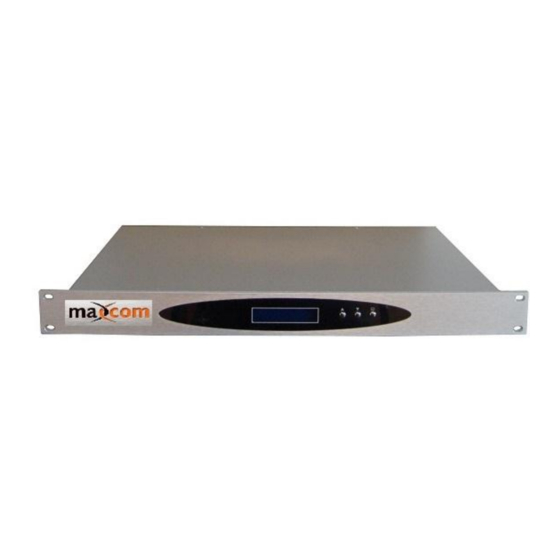
The MX4RR-LI reverse optical receiver is an indoor 1U structure, it has four
independent return path optical receivers, 4 optical inputs. 4 independent RF outputs
using F-type connectors. The output signal level may be adjusted by pressing the front
panel key, the adjustment range is 30dB.
MX4RR-LI
Advertisement
Table of Contents

Related Manuals for Maxcom MX4RR-LI


Summary of Contents for Maxcom MX4RR-LI
- Page 1 II Performance Introductions: 1、Structure Characteristics The MX4RR-LI reverse optical receiver is an indoor 1U structure, it has four independent return path optical receivers, 4 optical inputs. 4 independent RF outputs using F-type connectors. The output signal level may be adjusted by pressing the front...
- Page 2 Functions Displays information, parameters and working status: ·RFoG ReturnRX (MAXCOM) initial state, indicating the RFoG reverse optical receiver ·MODEL: MX4RR-LI SN: (xxxxxxxx) indicating the optical receiver LCD Display module and cascade ·RX(x) ATT: (x)dB Power In: (low / x dBm)
- Page 3 Check Mark Indicates the fiber connector type Indicates the operating mode, there are two selections: Mode ·RFoG Low power receive ,ode, receiving optical power is Selection -20~-5dBm; Switch ·Normal The normal output receive pattern, the receive optical power is -5~0dBm, with AGC Power Switch Power and display for electric circuit, AC 110V, 60Hz and Socket...
- Page 4 III Specifications Items Unit Performance Remark Optical Wavelength 1260~1590 Recommended range, Input Power Range -20~0 receiver will operate to -27dBm Return Loss >45.0 Power Instruction Precision RF Passband 5~65 Input optical power is Output Level dBmV ≥20 -20dBm, ATT is 0dB, 4% Flatness ≤±0.75 Output Return Loss...
- Page 5 IV Operating method 1、 Open box inspection The low power return optical receiver produced by Maxcom undergoes strict production checks, carefully packed before leaving the plant. There is an operating manual and appendix in the packing case. After receiving the equipment, the user should inspect the packing box.
- Page 6 4、 Mode Selection Switch Optical receiver’s rear panel is equipped with a mode selector switch. The switch sets the status to determine the receiver’s working mode—— RFoG (high sensitivity) mode, or Normal mode. ·RFoG Low power receive pattern, the received optical power range is -20~-5dBm ·Normal Normal power receive pattern, the received optical power range is...
- Page 7 high or the transmitter’s modulation index has increased. If affected by this situation, you may need to adjust the attenuator on the optical receiver, adjust the receiver output power to appropriate level. This equipment should be installed and serviced by personnel familiar with RF and optical equipment, and trained for laser safety! Provided by: Mega Hertz 800-883-8839 info@go2mhz.com...
Need help?
Do you have a question about the MX4RR-LI and is the answer not in the manual?
Questions and answers