Table of Contents
Advertisement
Quick Links
Features
Easy Installation
Loop power supply
Both side
isolate control
Designed to comply with EN 54-17
Description
VG-6777 Digital Isolate Interface monitors the
short circuit fault at the loop detection zone ,It
has both side isolate function ,if detects the
short circuit on loop it will isolate that side to
ensure loop communication signal will not be affected or interrupt by short-circuit fault. When the short circuit fault is
removed, the isolate interface will automatically restore loop.
Technical data
Operating Voltage:
Standby Current:
Isolate holding current
Action condition
Wiring
Temperature range:
Humidity:
Isolate Indication:
IP Rating:
Installation Base
Note:The VG-6777 Isolate interface is working with V-GREAT Digital Protocol
Installation
Dimensions:Showing on Fig.1
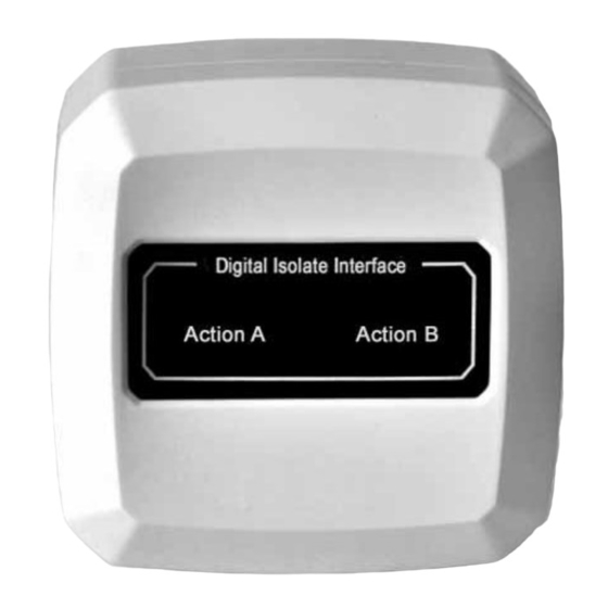
VG-6777 Digital Isolate Interface
18-28V(Modulated-pulse)
≤1mA
≤10mA
Isolate input/output side short circuit or loop voltage ≤7.5V
Two-wire(non-polarized)
-10℃~50℃
≤95%RH, (40±2℃)No condensation
Active A or Active B LED illuminates steadily.
32
VG-6618
Fig.1
1
Installation and Operation Manual V1.05
V1.05
Advertisement
Table of Contents

Related Manuals for V-GREAT VG-6777

Summary of Contents for V-GREAT VG-6777
- Page 1 Two-wire(non-polarized) Temperature range: -10℃~50℃ ≤95%RH, (40±2℃)No condensation Humidity: Isolate Indication: Active A or Active B LED illuminates steadily. IP Rating: Installation Base VG-6618 Note:The VG-6777 Isolate interface is working with V-GREAT Digital Protocol Installation Dimensions:Showing on Fig.1 Fig.1 V1.05...
- Page 2 VG-6777 Digital Isolate Interface Installation and Operation Manual V1.05 Mounting: Warning: Please disconnect the loop power in order to avoid control panel broken by short circuit when mounting Base. 1.Make sure the mounting direction mark “↑” on Base is upwards .
- Page 3 VG-6777 Digital Isolate Interface Installation and Operation Manual V1.05 will emitting. And A side of Isolate Interface D also start to isolate. Fig.4 Testing Warning:Power is switched on after all devices are installed completely. Isolate test: The LED indicator “Active A” or “Active B” will emitting when apply the short circuit to corresponding side of isolate Interface.
- Page 4 VG-6777 Digital Isolate Interface Installation and Operation Manual V1.05 Limited Warranty We warrants that the product will be free of charge for repairing or replacing from defects in design, materials and workmanship during the warranty period. This warranty doesn’t cover any product that is found to have been improperly installed or used in any way not in accordance with the instructions supplied with the product.
Need help?
Do you have a question about the VG-6777 and is the answer not in the manual?
Questions and answers