Table of Contents
Advertisement
Quick Links
Operating Manual ATOS VR
Operating Manual
Read before setup or flight!
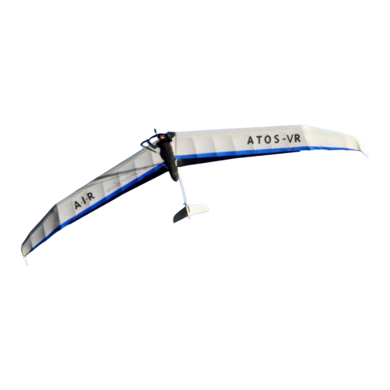
Congratulations and welcome to the ATOS - family! The ATOS VR you have purchased is a high-quality
aircraft. So that you can get the best out of your ATOS VR and avoid damage while setting up, you'll find
it helpful to study the following manual closely. If you have difficulty or problems, your A.I.R team stands
ready to help you.
A-I-R USA LLC Edition: 12/12/05
Advertisement
Table of Contents

Related Manuals for A-I-R ATOS VR

Summary of Contents for A-I-R ATOS VR
- Page 1 Congratulations and welcome to the ATOS - family! The ATOS VR you have purchased is a high-quality aircraft. So that you can get the best out of your ATOS VR and avoid damage while setting up, you'll find it helpful to study the following manual closely. If you have difficulty or problems, your A.I.R team stands ready to help you.
-
Page 2: Setup Procedure
On wet roads and particularly with salt on the roads a waterproof glider bag is recommended - of course available from your local ATOS Dealer. Otherwise the ATOS VR should be dried as soon as possible to avoid damp stains in the sail and corrosion of the metal parts. Also the D-cells and ribs can take up moisture if they are wet or in high humidity and should be dried as soon as possible. - Page 3 3. Stand the ATOS VR up on the control frame. Important with uneven area: The wing must stand stably on the control frame. If it should tilt against the top of the upright connection, the D-cell can be damaged or the sail compressed.
- Page 4 7. Connect the sail rings to the bracket at the top of the control frame by depressing the pin in the center of that bracket (picture below). Make sure you hear the pin snap shut locking the rings in place. Note : Be very cautious of the flaps.
- Page 5 stinger. 10. Collect the aluminum tube and carbon ribs and wing tip for one wing. The left wing components are marked with red spots - the right with green. On the ribs, there's an indication on the colored spot, of the edge that goes up.
- Page 6 12. Slide the tube in aligning the key and the key slot until the tube bottoms out (pictured above). The carbon leading edge shell packs along the front edge. You'll be able to find it just outside the end of the D-cell as shown, slide it out along the aluminum extension tube.
- Page 7 15. Now you want to rotate the tip lever around the tip wand end. Grasp the upper lever end rope in your left hand and the lower lever end rope in your right. The best action is to pull the left hand to the rear and guide the right hand into the sail and against the wand.
- Page 8 17. Next go to the end of the D-cell and open the sail so that you can see how the interior ribs are folded. Note the order as it is important when folding up the glider that the last rib is the last one to fold in. Open the ribs and the first one to connect is the last rib on the D-cell.
-
Page 9: Pre-Flight Check
19. Now insert and cam in place the larger of the 2 outboard ribs and then the smaller. If you look in the sail, you can see the aluminum stop that they go against. Keep the sail aligned at the rear. 20. - Page 10 2. Connection of the elastic to the spoiler lever. 3. Examine Spoiler levers for operation smoothness. 4. Open the sail between behind the spoiler rib in order to be able to see into the wing. Examine whether the spoiler rope runs freely. Important: The spoiler rope must run unhindered along the D-cell. It could be bound up e.g.
- Page 11 6. Remove the tip and then slide the extension tube out. Place the ribs, tip, and extension at the front of the glider so that they are not accidentally stepped on. 7. While standing behind the sail, pull the sail out along the D-cell and then fold over as shown so that the outer spoiler lays white side to white side against the main spoiler.
-
Page 12: Flight Characteristics
9. CAREFULLY release the nose latch and slowly lower the D-cells to the ground by opening the latch. Again be careful not to let the latch snap open and injure you. 10. Undo both zippers leaving the slide to the top end of the zipper. You must be careful of where the slides are so that they don't get crushed between the keel and the D-cells when closed up. - Page 13 Having a good airspeed indicator and understanding of your polar will be very important in getting the most performance from your glider. The ATOS VR is not suitable for Aerobatics. The glider can easily be over-sped and thereby, the structure overloaded! Thermaling and high-speed flight When thermaling set the flaps at 15-25°...
-
Page 14: General Comments
setting and letting the glider stall to the ground. Raising the hands too high on the control frame uprights. They should be in the area of the weak links. Be cautious of going to the uprights by moving one hand first and then pulling yourself up with that hand. - Page 15 After adjusting the spoiler rope also examine and adjust the stopper rope (see below). Adjustment and function of stopper rope The stopper rope is in place to maintain small loads at the spoiler rib and spoiler lever. The maximum excursion of the spoilers is 80° and is limited by a rope connection between the spoiler rope and an anchor on from blowing over on it's back should you forget the bungie.
- Page 16 a depression, or any visual fine-line crack would be indicative of damage. This is all particularly important around the spar caps and the roving that holds the pivot points in place. Removal of the sail is necessary to allow good examination from the rear of the D-cell of the spar caps' adhesion to the D-cell. Any suspected or observable damage in any of these areas should be brought to your dealer immediately for determination of repair or replacement.
-
Page 17: Technical Data
Operation limits ATOS VR max. permissible speed of flap 0 - 15° 90 km/h max. permissible speed of flap 70° 90 km/h safe load factor +4 g permissible takeoff weight 90-181,5 kg Technical data Span: 13,8 m Wing aspect ratio: 13.5 Flap positions 0 - 70°...
Need help?
Do you have a question about the ATOS VR and is the answer not in the manual?
Questions and answers