
Related Manuals for Fobitec WS-2

Summary of Contents for Fobitec WS-2
- Page 1 User Manual for indicator WS-2 www.fobitec.gr – info@fobitec.gr Tel. 0030 2310 795686 Fax. 0030 2310 795687 INDUSTRIAL AREA OF SINDOS THESSALONIKI 57022 P.O. BOX 1217 GREECE...
-
Page 2: Table Of Contents
CONTENTS PROLOGUE ..............................3 USEFUL INFORMATION ..........................3 DESCRIPTION OF INDICATOR WS-2 ..................... 4 KEYBOARD FUNCTION ..........................5 SYSTEM PARAMETERS ......................6 “Ad.FiLt”: ADC Filter, Converter filter AD..............6 “Ad.GAIn”: ADC Gain, Converter gain AD ..............6 “Ad.noiS.”: ADC noise, Noise level at the load cell input ........6 “Ad.driF.”: ADC thermal drift correction.............. - Page 3 ...................... 12 AUTOMATED WEIGHING COUNTER ................13 ERROR CODES ............................13 BASIC TECHNICAL CHARACTERISTICS OF THE UNIT WS-2 ............15 DIAGRAM 1 ............................16 DIAGRAM 2 ............................17 DIAGRAM 3: CONNECTION OF OUTPUT UNIT EXPANSIONS WSXT-2 ......18 BASIC TECHNICAL CHARACTERISTICS OF WSXT-2 UNIT ............18...
-
Page 4: Prologue
PROLOGUE Thank you very much for choosing our electronic weighing scale. In order to use this scale properly, we would like to ask you to read these instructions manual carefully. USEFUL INFORMATION The indicator should be placed in a dry place in order to be protected from rain and from getting wet, and also from sun exposure for a long period of time. -
Page 5: Description Of Indicator Ws-2
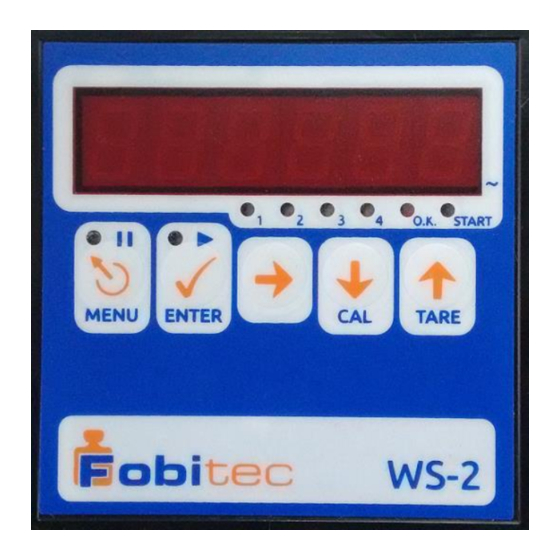
DESCRIPTION OF INDICATOR WS-2 1) 6 digit LED display Display of weight: “-99999” .. “999999” with adjusted decimal point. Display of parameters, messages, etc. 2) The dot at the bottom right of the display LED serves as an indication of “instability” of the weight indication. -
Page 6: Keyboard Function
KEYBOARD FUNCTION In the majority of operations, the keys have the following functions: MENU: Enter / exit the menu of parameters adjustment, cancelation of numerical alteration, return a level back to the menu structure, temporary pause/ cancelation of the weighing process. Equipped with LED, which lights up / flashes according to the user‟s operations. -
Page 7: System Parameters
SYSTEM PARAMETERS “SYS.Par.”: System parameters System parameters are set on the menu “SYS.Par.”, on which we have access when it is at weighing mode and we press the keys “NEXT” and “MENU” simultaneously for 7 seconds. This menu consists of critical parameters for the function of the indicator. “Ad.FiLt”: ADC Filter, Converter filter AD The higher it is, the lower the weighing sample rate per second. -
Page 8: Ad.drif.": Adc Thermal Drift Correction
“Ad.driF.”: ADC thermal drift correction, Thermal drift correction for the converter AD Displayed units per second Value: 0,0 .. 1,0 Default: 0,0 When it is higher than 0, it eliminates the very slow changes in the indication that usually happens due to the thermal drift of the load cell and the converter AD. For example, if it is 0,2 it eliminates the drift lower or equal to 0,2 units per second, which means 1 unit per 5 seconds, while if it is 0,5 it eliminates 0,5 units per second, which means 1 unit per 2 seconds. -
Page 9: Zer.o.id": Zero Output Id
“P.3 O.Id”: Product #3 Output ID Relay output serial number for product #3. If it is 0, there is no output for this material Value: 0 .. 4 Default: 3 “P.4 O.Id”: Product #4 Output ID Relay output serial number for product #4. If it is 0, there is no output for this material Value: 0 .. -
Page 10: Batch": Batch Mode
Description of formulas functions (Silo): We define the kilos of each product for example P1: 10 kilos, P2:5 kilos and P3: 20 kilos. Once we set the system on, the output relay of product 1 is activated up to the kilos we have set (10 kg in our example). -
Page 11: Comm.": Communication Mode
“Comm.”: Communication Mode Function of communication port (RS232) Value: 0 .. 3 Default: 0 0 : without communication 1 : recording of weighing history, printing of the last weighing with key selection „ENTER‟ at rest mode. 2 : recording of weighing history, automatic printing at the end of the weighing. 3 : Continuous transmission of data on display or computer, “repeater mode”. -
Page 12: User Parameters
USER PARAMETERS “USr.PAr.”: User Parameters In the menu “Usr.Par.” we have access during the normal operation, when the system is at rest mode (weight indication without operation of the weighing procedure) and we press briefly the key "MENU". “For. 1” ... “For. 12”: Formula 1 ... Formula 12. The message “F. -
Page 13: Filter": Filter
“FILtEr”: Filter, It is not displayed when System Parameter Pass == 0. Integration filter for algorithm approximation of weight and vibration / noise rejection, the higher it is, the slower the weight approximation. Value: 0 .. 10 Default: 1 “A.tArE”: Auto Tare. It is not displayed when System Parameter Pass == 0. -
Page 14: Automated Weighing Counter
AUTOMATED WEIGHING COUNTER The counter increases its value every time a successful automated weighing procedure start occurs. In order to be seen, the user should press for an instant the “NEXT” key, while the indicator shows the current weight, or the scale is empty, or during an automated weighing procedure. The indication shows “Cn xxx”... - Page 15 ADC Converter Error Possible reasons: Similar to error 1. Solution: If the problem persists after restart, it possible that the converter AD is damaged. System parameters of corresponding outputs error ( Output ID Error ) Possible reasons: Some parameters that correspond to automation outputs with the Relay of the device have a value error (overlays, two outputs addressed to the same Relay).
-
Page 16: Basic Technical Characteristics Of The Unit Ws-2
BASIC TECHNICAL CHARACTERISTICS OF THE UNIT WS-2 Power Supply : 10 ... 24Vac, 10 ... 32Vdc (+/- 10% ) Maximum consumption: 500mA @ 10Vac / 10Vdc, 200mA @ 32Vdc / 24Vac Type of connection: 6or 4 cables 5Vdc ± 5%, 120mA ( up to 8 load cells of 350Ω ) Power supply: „LOAD CELL‟... -
Page 17: Diagram 1
CONNECTIONS DIAGRAM 1 Thread “SERIAL”: Connection of serial port RS-232. Thread “EXP.”: Connection of expansion units Thread “LOAD CELL”: Connection of load cell with 6 cables (compensates the weighing error due to the cable). Thread “REMOTE”: Connection of buttons START and STOP in the automation input. The weighing procedure starts with an instant touch of START and instantly stops by pressing STOP. -
Page 18: Diagram 2
DIAGRAM 2 Thread “LOAD CELL”: Load cell connection 4 cables. The connections S-,S+ must be bridged with the I-, I+ equivalently ( with short cables on the thread). Thread “REMOTE”: Connection of switch START/STOP in the automation input. The weighing procedure starts by turning off the switch and stops immediately by turning it on. Optional connection of formula selector. -
Page 19: Diagram 3: Connection Of Output Unit Expansions Wsxt-2
Up to three WSXT-2 units, which supply 4 Relay outputs each, can be connected. These units can have the same power supply with the unit WS-2, if it is capable of supplying power to them. They‟re controlled via the 3-pole terminal „EXP.‟ which the WS-2 displays, by connecting the connections one by one, as they are numbered.
Need help?
Do you have a question about the WS-2 and is the answer not in the manual?
Questions and answers