Table of Contents
Advertisement
Quick Links
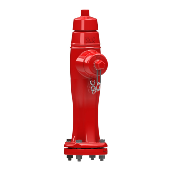
AVK SERIES 67 - HIGH PRESSURE,
POST/FLUSHING HYDRANT
FIELD MAINTENANCE AND
INSTRUCTION MANUAL
TABLE OF CONTENTS
EXPLODED ASSEMBLY / PARTS LIST
INTRODUCTION / DESCRIPTION
RECEIVING AND STORAGE
INSTALLATION AND TESTING
- INSTALLATION
- TESTING
OPERATION AND MAINTENANCE
- HYDRANT TOOLS
- OPERATION
- MAINTENANCE PROCEDURES
- INSPECTION
REPAIR PROCEDURES
- NOZZLE REPLACEMENT
- TRAFFIC REPAIR KIT
- MAIN VALVE REPLACEMENT
OPTIONAL EQUIPMENT
- EXTENSION KITS
TROUBLESHOOTING GUIDE
PARTS AND SERVICE
WARRANTY
American AVK Company
An ISO 9001 registered company
- LUBRICATION
- DISASSEMBLY FOR INSPECTION
- REASSEMBLY AFTER INSPECTION
Maintenance Manual Series 67
*Subject to change without notice. (rev.04/10 B)
Advertisement
Table of Contents

Related Manuals for AVK 67 Series


Summary of Contents for AVK 67 Series
- Page 1 AVK SERIES 67 - HIGH PRESSURE, POST/FLUSHING HYDRANT FIELD MAINTENANCE AND INSTRUCTION MANUAL TABLE OF CONTENTS EXPLODED ASSEMBLY / PARTS LIST INTRODUCTION / DESCRIPTION RECEIVING AND STORAGE INSTALLATION AND TESTING - INSTALLATION - TESTING OPERATION AND MAINTENANCE - HYDRANT TOOLS...
- Page 2 page 1...
- Page 3 Item No. Description Material Weathershield Bolt 304 Stainless steel Weathershield Grey Iron, ASTM126, Class “B” Valve Seat O-ring Hose Nozzle Cap Grey Iron, ASTM126, Class “B” Hose Nozzle Copper Alloy Hose Nozzle Cap Gasket Hose Nozzle O-ring Set Screw - (Nozzle) 304 Stainless steel Chain Assembly Zinc Plated Steel...
-
Page 4: Introduction / Description
Inspect the hydrants upon receipt for damage in shipment. Note any damage on the bill of lading and have the driver sign it. Notify American AVK. Unload all of the hydrants carefully to avoid damage. Verify that the hydrants have the correct direction to open, the correct nozzle configuration and threads, the correct operating nut size and shape, the correct depth of bury, and the correct inlet connection. - Page 5 2' min. Concrete collar for protection on all hydrant installations. 2" min. 6" Curb Bury Drain Detail: Caution: When pouring thrust block, do not cover Concrete drain holes. 1/3 cubic yard drain field Supply Valve rock. C o n c r e t e thrust block Concrete C o n c r e t e...
-
Page 6: Pressure Testing
PRESSURE TESTING American AVK Recommended Hydrant Testing Procedure AAVK recommends that AWWA M17, "Installation, Field Testing, and Maintenance of Fire Hydrants", chapters 4.3 and 4.4 be followed for field testing and placing the hydrant in service. The following is excerpted from AWWA M17 for the... - Page 7 Series 67 T-Wrench, for Main Valve removal/replacement. 67-065-59 Series 67 Hydrant Wrench, for Thrust Nut removal/replacement, 67-080-59 hydrant operation, and Cap removal/replacement. METRIC AND INCH WRENCH REQUIREMENTS FOR AMERICAN AVK HYDRANTS PART INCH SIZE METRIC SIZE Weathershield Retaining Bolt (Allen) 5/16”...
- Page 8 OPERATION The American AVK Series 67 Post / Flushing Hydrant is designed to be an easily operated, low torque, high flow post hydrant. It will not require excessively high loads to operate. It is possible to damage the hydrant by forcing it beyond its normal operational limits.
-
Page 9: Maintenance Procedures
MAINTENANCE PROCEDURES The American AVK Series 67 Post / Flushing Hydrant is designed to be a trouble free, easy to maintain hydrant. The following steps are recommended to provide trouble free operation. LUBRICATION CAUTION: For grease servicing, ensure that the Weathershield bolt has been loosened to prevent damage to the internal O-rings. -
Page 10: Disassembly For Inspection
INSPECTION DISASSEMBLY FOR INSPECTION: The American AVK Series 67 Post / Flushing Hydrant is designed to be a trouble free, easy to maintain hydrant. The following steps are recommended to provide trouble free operation. WARNING: For all of the following repair procedures, the hydrant must be isolated or the system depressurized and drained before removing the hydrant components. - Page 11 3. Remove the Weathershield (F2), by removing the Weathershield Bolt (F1), using a 5/16" or 8mm Allen wrench. (See Fig. 5) 4. Loosen the Thrust Nut Retaining Screw (F59), using a 5/32" or 4mm Allen wrench. Using the AVK Series 67 hydrant wrench, remove the Thrust Nut (F76), and Thrust Nut O-ring (F52). (See Fig. 6) 5.
- Page 12 DISASSEMBLY FOR INSPECTION: (continued) MAIN VALVE INSPECTION Fig. 5 Fig. 6 Fig. 7 F500 F501 Series 67 T-Wrench F508 F507 F504 F506 Fig. 9 Fig. 10 Fig. 11 F505 F510 F515 F517 F516 F518 Fig. 8 Fig. 12 page 11...
- Page 13 3. Gently pull the pull the Cap/Nozzle assembly out until the nozzle lugs are in line with the nozzle section lugs. 4. Using the AVK hydrant wrench or adjustable hydrant wrench, loosen the Hose Nozzle Cap (F19) in a counter clockwise direction.
- Page 14 O-ring (F73), and mounting hardware (F31,F34,F506) need to be replaced. F506 2. Using the AVK Series 67 Hydrant Wrench, fully open the hydrant to allow better access to the lower end of the Upper Stem Rod (F503). Visually inspect the Upper Stem F38, F507, F508 Rod for damage.
-
Page 15: Repair Procedures
REPAIR PROCEDURES TRAFFIC REPAIR: (continued) 9. Gently slide the Nozzle Section over the Upper Stem Rod, taking care not to displace the Stem Seal O-rings, until it comes to rest on the Lower Barrel. Note: Ensure that the Flange O-ring is located in the groove of the Lower Barrel. 10. - Page 16 REPAIR PROCEDURES MAIN VALVE REPLACEMENT: WARNING: For all of the following repair procedures, the hydrant must be isolated or the system depressurized and drained before removing the hydrant components. Failure to do so may cause pressure to be released resulting in severe injury or death.
- Page 17 OPTIONAL EQUIPMENT Machined lip on EXTENSION KITS: Breakable Flange WARNING: For all of the following repair procedures, the hydrant must be isolated or the system depressurized and drained before removing the hydrant components. Failure to do so may cause pressure to be released resulting in severe injury or death.
-
Page 18: Troubleshooting Guide
Hydrant or supply vale is not fully open. Corrective action: Verify that the hydrant is fully open. The AVK Series 67 hydrant main valve hits the stop in the base after approximately10 turns. Also locate and verify that the isolation valve is fully open. -
Page 19: Parts And Service
PARTS AND SERVICE For information on parts and service for your area contact American AVK. Make a note of the valve model number and size located on the valve and contact: American AVK Company 2155 N. Meridian Blvd. Minden, NV 89423...
Need help?
Do you have a question about the 67 Series and is the answer not in the manual?
Questions and answers