Table of Contents
Advertisement
Quick Links
Read the Instruction Manual
INSTRUCTION MANUAL
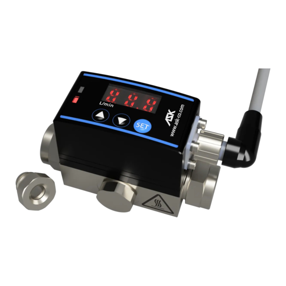
DIGITAL FLOW SENSOR
〔DFS-*-O/W〕
2. Safety precautions
8. How to configure
10. Specifications
FOR
Contents
ASK CORPORATION
1-34-16, Higashi-Shinagawa, Shinagawa, Tokyo,
Tel: 03-3471-4845 Fax : 03-5463-7022
Branch: Osaka
PB97001E-A
2011/06/28
140-0002, Japan.
1
Advertisement
Table of Contents

Subscribe to Our Youtube Channel
Summary of Contents for Ask DFS-1
- Page 1 5. Description of Model-No. 6. Wiring connection 7. Explanation of function 8. How to configure 9. How to remove a contaminant 10. Specifications ASK CORPORATION 1-34-16, Higashi-Shinagawa, Shinagawa, Tokyo, 140-0002, Japan. Tel: 03-3471-4845 Fax : 03-5463-7022 Branch: Osaka Read the Instruction Manual...
- Page 2 For best results, please refer to this manual before using this product. 2. Safety precautions Model Precautions DFS-1 The maximum pressure of this model is 3 MPa (30 bar). Do not exceed this maximum pressure rating. Doing so may cause the sensor to explode and result in possible physical injury.
- Page 3 4 times on the downstream side. Do not install curved, confluence, or branch piping (, that is, elbow, tee, throttle valve ), near the outlet. Model Upper Flow Passage Lower Flow Passage DFS-1 > 100 mm > 40 mm DFS-2 > 140 mm >...
- Page 4 6: Rc 3/4 8: Rc 1 ③ FLOW MEDIUM O: Hydraulic oil, Lubricating oil W: Water, Water-soluble cutting oil ④ CUSTOM SPECIFICATIONS Please ask us. 6. Wiring connection M12x1 4-pin connector ① (+)POWER SOURCE: DC +12~24 V (allowable oscillation ±10 %) ②...
- Page 5 DFS-*-O/W 7. Explanation of function Flow rate measurement The sensor initialized for 7 seconds after it is connected to a power supply. You can start using the sensor to measure flow after the sensor completes this initialization period. A seven-segment LED display indicates the flow rate. If the flow rate drops below the lower limit or exceeds the upper limit of the specified range, the LED blinks 「...
- Page 6 DFS-*-O/W 8. How to configure Press and hold for 2 seconds to switch modes. Press to select one of 4 headings within a configuration mode. (Alarm, Display, Output type or Cancel) Alarm Configure Output/Alarm Switch to output/alarm mode. Press to select a value. Hold to scroll through the numbers quickly.
- Page 7 DFS-*-O/W 9. How to remove a contaminant You can remove a contaminant from the magnet of the rotor by blowing air. You do not need to disconnect the piping from the sensor before performing this procedure. (1) Remove the cap installed on the center of the body (see below). (2) Using an air blower, blow out the contaminant toward the downstream side of the sensor.
- Page 8 DFS-*-O/W 10. Specifications General Specification DFS-1 DFS-2 DFS-3 DFS-6 DFS-8 CONNECTING Rc 1/8 Rc 1/4 Rc 3/8 Rc 3/4 Rc 1 THREAD MAXIMUM FLOW RATE (L/min) MEASUREMENT 0.2~1 1~10 2~20 5~50 10~100 RANGE (L/min) 3 (if a metal/plastic cap is installed)
Need help?
Do you have a question about the DFS-1 and is the answer not in the manual?
Questions and answers