Daikin DCC Series Installation Instructions Manual
Lighting commercial packaged heating and cooling unit
Hide thumbs
Also See for DCC Series:
- Installation instructions manual (48 pages) ,
- Service instructions manual (135 pages) ,
- Installation instructions manual (48 pages)
Table of Contents
Advertisement
Quick Links
DCC
SERIES
LIGHT COMMERCIAL PACKAGED HEATING AND COOLING UNIT
15 to 25 T
ON
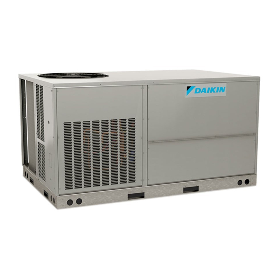
NOTE: 15 & 20 ton model shown in picture.
25 ton model has 2 fans.
ATTENTION INSTALLING PERSONNEL:
Prior to installation, thoroughly familiarize yourself with
this Installation Manual. Observe all safety warnings.
During installation or repair, caution is to be observed.
It is your responsibility to install the product safely and
to educate the customer on its safe use.
RECOGNIZE THIS SYMBOL
AS A SAFETY PRECAUTION.
These installation instructions cover the outdoor installation
of single package heating and cooling units. See the
Specification Sheet applicable to your model for information
regarding accessories.
*NOTE: Please contact your distributor or our website for
the applicable Specification Sheet referred to in this manual.
IOD-1028A
03/2019
Our continuing commitment to quality products may mean a change in specifications without notice.
©2018 - 2019
5151 San Felipe St., Suite 500, Houston, TX 77056
www.daikinac.com
INSTALLATION INSTRUCTIONS
O
NLY PERSONNEL THAT HAVE BEEN TRAINED TO INSTALL
(
, "
")
REPAIR
HEREINAFTER
SERVICE
SHOULD SERVICE THE EQUIPMENT
FOR ANY INJURY OR PROPERTY DAMAGE ARISING FROM IMPROPER SERVICE OR
. I
SERVICE PROCEDURES
F YOU SERVICE THIS UNIT
FOR ANY INJURY OR PROPERTY DAMAGE WHICH MAY RESULT
JURISDICTIONS THAT REQUIRE ONE OR MORE LICENSES TO SERVICE THE EQUIPMENT
,
SPECIFIED IN THIS MANUAL
ONLY LICENSED PERSONNEL SHOULD SERVICE THE
. I
EQUIPMENT
MPROPER INSTALLATION
THE EQUIPMENT SPECIFIED IN THIS MANUAL
SERVICE OR REPAIR THE EQUIPMENT SPECIFIED IN THIS MANUAL WITHOUT PROPER
TRAINING MAY RESULT IN PRODUCT DAMAGE
.
INJURY OR DEATH
PROP 65 WARNING
FOR CALIFORNIA CONSUMERS
Cancer and Reproductive Harm -
www.P65Warnings.ca.gov
Replacement Parts .........................................................2
Safety Instructions .........................................................2
General Information .......................................................2
Unit Location ...................................................................3
Clearances ......................................................................5
Roof Curb Post-Installation Checks .............................6
Roof Top Duct Connections ..........................................6
Rigging Details ...............................................................6
Electrical Wiring .............................................................7
Circulating Air and Filters ..............................................9
Condensate Drain Connection ......................................9
Startup, Adjustments, and Checks .............................10
,
,
ADJUST
SERVICE OR
THE EQUIPMENT SPECIFIED IN THIS MANUAL
. T
HE MANUFACTURER WILL NOT BE RESPONSIBLE
,
YOU ASSUME RESPONSIBILITY
. I
N ADDITION
,
,
ADJUSTMENT
SERVICING OR REPAIR OF
,
OR ATTEMPTING TO INSTALL
,
,
PROPERTY DAMAGE
PERSONAL
WARNING
Index
,
IN
,
,
ADJUST
0140M00517-A
Advertisement
Table of Contents

Related Manuals for Daikin DCC Series


Summary of Contents for Daikin DCC Series
-
Page 1: Table Of Contents
INSTALLATION INSTRUCTIONS SERIES LIGHT COMMERCIAL PACKAGED HEATING AND COOLING UNIT 15 to 25 T NLY PERSONNEL THAT HAVE BEEN TRAINED TO INSTALL ADJUST SERVICE OR , “ ”) REPAIR HEREINAFTER SERVICE THE EQUIPMENT SPECIFIED IN THIS MANUAL SHOULD SERVICE THE EQUIPMENT HE MANUFACTURER WILL NOT BE RESPONSIBLE FOR ANY INJURY OR PROPERTY DAMAGE ARISING FROM IMPROPER SERVICE OR SERVICE PROCEDURES... -
Page 2: Replacement Parts
Specification sheets can be found at www.daikinac.com for nstaller Daikin brand products. Within the website, please select the Before installing this unit, please read this manual to residential or commercial products menu and then select the... -
Page 3: Unit Location
To assure that your unit operates safely and efficiently, it 4. File the claim with the following supporting documents: must be installed, operated, and maintained in accordance a. Original Bill of Lading, certified copy, or indemnity with these installation and operating instructions, all local bond. - Page 4 contaminated by compounds containing chlorine reCautiOns or fluorine. Common sources of such compounds • Do not stand or walk on the unit. include swimming pool chemicals and chlorine • Do not drill holes anywhere in panels or in the base bleaches, paint stripper, adhesives, paints, varnishes, frame of the unit (except where indicated).
-
Page 5: Clearances
• Sufficient structural support must be determined prior to locating and mounting the curb and package unit. • Ductwork must be constructed using industry LIFT OVER APPROXIMATE CENTER OF UNIT guidelines. The duct work must be placed into the SPREADER BARS MUST BE USED WITH roof curb before mounting the package unit. -
Page 6: Roof Curb Post-Installation Checks
CAUTION O NOT LIFT UNITS TWO AT A TIME ROVISIONS FOR FORKS HAVE BEEN 72” INCLUDED IN THE UNIT BASE FRAME INIMUM FORK LENGTH IS PREVENT DAMAGE TO THE UNIT Provisions for forks have been included in the unit base frame. -
Page 7: Electrical Wiring
iGGinG emOval CAUTION CAUTION HEN UNIT IS SUSPENDED BOARDS AND SHIPPING BRACE WILL DROP WHEN , STAND CLEAR. SCREWS ARE REMOVED O PREVENT PERSONAL INJURY O PREVENT DAMAGE TO THE UNIT DO NOT ALLOW CRANE HOOKS AND EMOVE FORK HOLE BRACKETS BOARDS AND SHIPPING BRACE FROM BOTTOM SPREADER BARS TO REST ON THE ROOF OF THE UNIT OF UNIT BEFORE PLACING UNIT ONTO CURB... - Page 8 Main power wiring should be sized for the minimum circuit ampacity shown on the unit’s data plate. Size wires in accordance with the ampacity tables in Article 310 of the Line voltage connects National Electrical Code. If long wires are required, it may to middle contactor be necessary to increase the wire size to prevent excessive on 460v and 575v...
-
Page 9: Circulating Air And Filters
3. Use #18 AWG wire for 24V control wiring runs not WARNING exceeding 75 feet. Use #16 AWG wire for 24V control wiring runs not exceeding 125 feet. Use #14 AWG AILURE OF UNIT DUE TO OPERATION ON IMPROPER LINE VOLTAGE wire for 24V control wiring runs not exceeding 200 OR WITH EXCESSIVE PHASE UNBALANCE CONSTITUTES PRODUCT feet. -
Page 10: Startup, Adjustments, And Checks
WARNING MOVING MACHINERY HAZARD! Base Rail O PREVENT POSSIBLE PERSONAL INJURY OR DEATH DISCONNECT Open Vent 2” Min “OFF” POWER TO THE UNIT AND PADLOCK IN THE POSITION BEFORE SERVICING FANS See NOTE eatinG tartuP On new installations, or if a major component has been re- placed, the operation of the unit must be checked. - Page 11 current rating of the motor. The amperage must not exceed bstruCtiOns learanCe anD irinG the service factor stamped on the motor nameplate. The total Remove any extraneous construction and shipping materials airflow must not be less than that required for operation of that may be found during this procedure.
- Page 12 NOTE: Future adjustments should be made by loosening the belt tension and increasing or decreasing the pitch diameter of the sheave by half or full turns as required. Readjust belt tension before starting drive. *Apply force to the center of the span. t = Span length, inches C = Center distance, inches VL &...
- Page 13 Final System Checks 6. Slowly lower the cooling temperature until first stage COOL (LOW COOL) starts. The blower, both fans, 10.Check to see if all supply and return air grilles are and first stage compressor should now be operating. adjusted and the air distribution system is balanced The blower should be operating in low speed at 1175 for the best compromise between heating and cooling.
- Page 14 1. Tighten all belts, set screws, and wire connections. abinet inish aintenanCe 2. Clean evaporator and condenser coils mechanically Use a fine grade automotive wax on the cabinet finish to or with cold water, if necessary. Usually any fouling maintain the finish’s original high luster. This is especially is only matted on the entering air face of the coil and important in installations with extended periods of direct can be removed by brushing.
- Page 15 APPENDIX A BLOWER PERFORMANCE DATA BELT DRIVE - STANDARD DCC180 STANDARD TWO-SPEED BELT DRIVE AT HIGH SPEED TURNS OPEN ESP, In H 7203 2.18 6718 1.94 7306 2.54 6777 2.14 6257 1.80 5711 1.66 7477 2.97 6899 2.51 6323 2.10 5716 1.72 5103...
- Page 16 APPENDIX A BLOWER PERFORMANCE DATA — — BELT DRIVE - HIGH STATIC DCC180 HIGH STATIC BELT DRIVE - 2 SPEED AT HIGH SPEED TURNS OPEN (In W.C.) 6580 4.30 5.14 4.53 3.98 6930 6432 5908 6866 5.52 6382 4.80 5916 4.24 5370 3.68...
- Page 17 —- —- APPENDIX A ECONOMIZER PRESSURE DROP Airflow Pressure Drop of Downflow Economizer for 15 to 25 Ton Rooftop Units (100% Return Air) SCFM 4500 5000 5500 6000 6500 7000 7500 8000 8500 9000 9500 10000 (In WG) 0.15 0.18 0.22 0.27 0.32...
- Page 18 APPENDIX B ELECTRICAL DATA Compressor Compressor Optional Powered Electrical Outdoor Fan Motor Indoor Fan Motor Optional Electric Heat Power Supply Model Number Circuit 1 Circuit 2 Convienience Outlet Rating Type Part # 82.6 / 82.6 EHK3-31 21.6 / 28.8 60.0 / 69.3 100 / 112 2-speed EHK3-46...
- Page 19 APPENDIX B ELECTRICAL DATA Compressor Compressor Optional Powered Electrical Outdoor Fan Motor Indoor Fan Motor Optional Electric Heat Power Supply Model Number Circuit 1 Circuit 2 Convienience Outlet Rating Type Part # 103 / 103 EHK3-31 21.6 / 28.8 60.0 / 69.3 103 / 112 EHK3-46 32.4 / 43.2 90.1 / 104...
- Page 20 APPENDIX B ELECTRICAL DATA Compressor Compressor Optional Powered Electrical Outdoor Fan Motor Indoor Fan Motor Optional Electric Heat Power Supply Model Number Circuit 1 Circuit 2 Convienience Outlet Rating Type Part # 138 / 138 EHK3-31 21.6 / 28.8 60.0 / 69.3 138 / 138 EHK3-46 32.4 / 43.2...
- Page 21 APPENDIX C UNIT DIMENSIONS Model 15 Ton 88-7/32" 50-9/32" 5-5/32" 133-1/2" 20 Ton 25 Ton 133-1/2" 88-7/32" 53-9/32" 5-5/32" NOTE: 15 & 20 ton models have 3 fans. 25 ton models have 2 fans. 21” 60” 7” 48” 22” VERTICAL DISCHARGE (TOP VIEW)
- Page 22 WIRING DIAGRAMS DCC180*/DCC240* 208-230, 460, 575 / 3 / 60 2 SPEED Wiring is subject to change. Always refer to the wiring diagram on the unit for the most up-to-date wiring.
- Page 23 WIRING DIAGRAMS DCC180*/DCC240* 208-230, 460, 575 / 3 / 60 2 SPEED Wiring is subject to change. Always refer to the wiring diagram on the unit for the most up-to-date wiring.
- Page 24 WIRING DIAGRAMS DCC300* 208-230, 460, 575 / 3 / 60 2 SPEED THERMOSTAT WIRING SMOKE DETECTOR FIELD 2 STAGE COOLING CONTROL WIRING CLASS 2 SEN1 SENSOR 1 AUX A SUPPLY (LINE) VOLTAGE SENSOR 2 SEN2 AUX B 24 VAC SMK DET STAT OPTION CCR1...
- Page 25 wirinG DiaGrams fOr mODels with DDC COntrOls For complete information and installation instructions for models with DDC controls, see manual DK-DDC-TGD-XXX...
- Page 26 DCC180*/ DCC240* 208-230, 460, 575 / 3 / 60 2 SPEED WIRING DIAGRAMS POWER WIRING DIAGRAM LINE VOLTAGE DCC(180-240) CCAS1 CCH1 COMP 1 CCAS 2 CCH2 COMP 2 HVTB BK BK LINE VOLTAGE HIGH SPEED BC 2 SPEED FACTORY WIRING COMPONENT LEGEND HIGH VOLTAGE AUXILIARY LIMIT SWITCH...
- Page 27 WIRING DIAGRAMS DCC180*/ DCC240* 208-230, 460, 575 / 3 / 60 2 SPEED CONTROL WIRING DIAGRAM DCC(180-240)****V (COMP1 IN) (COMP1 OUT) (COMP2 OUT) (COMP2 IN) Wiring is subject to change. Always refer to the wiring diagram on the unit for the most up-to-date wiring.
- Page 28 WIRING DIAGRAMS DCC300* 208-230, 460, 575 / 3 / 60 2 SPEED Wiring is subject to change. Always refer to the wiring diagram on the unit for the most up-to-date wiring.
- Page 29 Start-up Checklist *Store in job file Date: ________________________________ Location: _______________________________________ Model Number: ________________________________ _______________________________________ Serial Number: ________________________________ _______________________________________ Technician: ________________________________ Unit #: _______________________________________ Pre Start-Up (Check each item as completed) Verify all packaging material has been removed. Remove all shipping brackets per installation instructions. Verify the job site voltage agrees with the unit serial plate.
- Page 30 Start-up Checklist Start-Up (Insert the values as each item is completed.) ELECTRICAL Supply Voltage L1 - L2 L2 - L3 L3 - L1 Circuit 1 Compressor Amps Circuit 2 Compressor Amps Blower Amps Condenser Fan Amps Fan 1 Fan 2 Fan 3 BLOWER EXTERNAL STATIC PRESSURE Return Air Static Pressure...
- Page 31 THIS PAGE INTENTIONALLY LEFT BLANK...
- Page 32 CUSTOMER FEEDBACK Daikin is very interested in all product comments. Please fill out the feedback form on the following link: https://daikincomfort.com/contact-us You can also scan the QR code on the right to be directed to the feedback page. Our continuing commitment to quality products may mean a change in specifications without notice.
Need help?
Do you have a question about the DCC Series and is the answer not in the manual?
Questions and answers