
Summary of Contents for OPW SiteSentinel Nano
- Page 1 Part Number: M2010-EU, Rev. 13 Issue Date: February 19, 2020 Supersedes: January 15, 2020 ® ® M2010-EU - SiteSentinel Nano Tank Gauge System Installation Guide 3.71.56.3 Bld 61.1...
- Page 2 . Download the latest revision if necessary. OPW Fuel Management Systems is a part of Dover Fueling Solutions. Copyright Information Copyright © 2019 Delaware Capital Formation, Inc. All Rights Reserved. DOVER, the DOVER logo are registered trademarks of Delaware Capital Formation, Inc., a wholly-owned subsidiary of Dover Corporation.
-
Page 3: Table Of Contents
Doc. No.: M2010-EU Rev.: 13 Page 3 of 149 Table of Contents Section 1 Get Started: Safety 1.1 Safety Warnings 1.2 Information Panels 1.3 Applicable Warnings 1.4 Hazardous Areas 1.5 I.S. Barriers - Special Conditions for Safe Use 1.6 Installer Safety 1.7 Precision Leak Test 1.7.1 Before Initial Inspection 1.7.2 Initial Inspection... - Page 4 Doc. No.: M2010-EU Rev.: 13 Page 4 of 149 3.2 Codes 3.3 Hazardous Area Definition 3.4 OM4 Technical Specifications 3.5 Product Certifications 3.6 OM4 Installation 3.7 OM4 Connections 3.8 Petro-Net Address Jumper Settings Section 4 Tank Alert (Overfill Alarm) 4.1 Safety Information 4.2 Tank Alert Specifications 4.3 Tank Alert Installation 4.4 Tank Alert Wiring...
- Page 5 Doc. No.: M2010-EU Rev.: 13 Page 5 of 149 7.2 Spacer Assembly (6-3/4 RA SS) and Adjustment 7.3 DMP Probe Cable Wiring to Nano I.S. Barrier Section 8 Density Measurement Float (DMF) 8.1 DMF Installation 8.2 Tank Thresholds Section 9 Sensor Support 9.1 IntelliSense™...
- Page 6 Doc. No.: M2010-EU Rev.: 13 Page 6 of 149 Warranty...
-
Page 7: Section 1 Get Started: Safety
Doc. No.: M2010-EU Rev.: 13 Page 7 of 149 Section 1 Get Started: Safety This manual will show the necessary steps to install your console, devices and peripheral options. Topics in this section include: "Applicable Warnings" on page 10 Hazardous Areas "I.S. -
Page 8: Safety Warnings
Doc. No.: M2010-EU Rev.: 13 Page 8 of 149 1.1 Safety Warnings This manual contains many important Safety Alerts. There can be a risk of injury or damage to property if you do not obey these alerts. The panels below show the types of safety warnings that can be seen and how each is specified. - Page 9 Doc. No.: M2010-EU Rev.: 13 Page 9 of 149 REMINDER: This panel shows information that has been given before in the manual that is important to show again. TIP: A step or procedure that is recommended to make another step or procedure easier.
-
Page 10: Applicable Warnings
The inside of OPW-FMS automatic tank-gauge system consoles contain high-voltage circuitry. NOTE: ONLY certified OPW technicians are authorized to install and program this automatic tank gauge system. This is necessary for warranty registration. DANGER: The coin cell battery may explode if mistreated. Do not recharge, disassemble or dispose of in fire. -
Page 11: Hazardous Areas
Doc. No.: M2010-EU Rev.: 13 Page 11 of 149 1.4 Hazardous Areas N F PA/N EC – C l a ss I, D i v. 1 & D i v. 2 Class I locations . Class I locations: Where flammable gases or vapors are or can be in the air in quantities sufficient to cause explosive or ignitable mixtures. -
Page 12: Barriers - Special Conditions For Safe Use
Refer to the applicable console Field Wiring Diagrams and Installation Guides for correct wiring of all Earth Ground and I.S. Ground terminals between the console and main electrical service panel.* * All OPW-FMS Installation Guides and Field Wiring Diagrams can be found at http://www.opwglobal.com/opw-fms/tech-support/manuals-how-to-videos... -
Page 13: Installer Safety
Doc. No.: M2010-EU Rev.: 13 Page 13 of 149 1.6 Installer Safety CAUTION: Incorrect installation can cause a risk of injury to installers and users of this equipment. Incorrect installation can result in environmental contamination or equipment damage. Read these instructions carefully! Refer to the National Electrical Code (NFPA No. -
Page 14: Precision Leak Test
The console Data Sheet found in the product container supplies important information about the tank gauge system. Keep the Data Sheet and OPW Technical Documentation CD in a safe location. A Field Wiring Diagram is included in the product container. Give this diagram to your installer or electrician. -
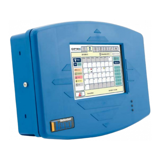
Page 15: Section 2 Sitesentinel® Nano® Console
Doc. No.: M2010-EU Rev.: 13 Page 15 of 149 ® ® Section 2 SiteSentinel Nano Console ® ® The SiteSentinel Nano console can monitor up to 12, 924B Tank-Probes and has two (2) relays that can be used at the same time. Since only AC power connections and Petro-Net communication connections are necessary, the console can be installed in many locations of a fueling facility. -
Page 16: Console Specifications
Doc. No.: M2010-EU Rev.: 13 Page 16 of 149 2.2 Console Specifications Console Specifications Power: 120/240 VAC +/- 10%, 50/60 Hz, 30 W Relay Contacts: 250V AC 10A Max. Operating Temperature: 0°C to 50°C (32°F to 122°F) 21 cm x 32.5 cm x 6 cm (8.3 inches x 12.8 inches x 2.4 Console Dimensions [H x W x D]: inches) 17.8 cm (7 inches) color LCD touch screen display Graph-... -
Page 17: Console Installation
Doc. No.: M2010-EU Rev.: 13 Page 17 of 149 2.3 Console Installation 2.3.1 Installation Instructions 1. Select an area to install the SiteSentinel® Nano® console on a wall in a safe indoor location. The display must be at approximately eye level and easily seen. a. - Page 18 Doc. No.: M2010-EU Rev.: 13 Page 18 of 149 NOTICE: Make sure to remove the main board and put it in a static-free area before you go to the next step. This will prevent damage to the main board components when you remove the knockouts.
-
Page 19: Installation Video
Doc. No.: M2010-EU Rev.: 13 Page 19 of 149 2.3.2 Installation Video Scan the code below or click the link to see the video, "Installation of an OPW Nano Tank Gauge." https://www.youtube.com/watch?v=qPZAe5_oWVk&feature=youtu.be IMPORTANT: Make sure the electrical wiring is connected on the left side of the console and the Tank-Probe and Smart-Sensor wiring is connected on the right side. - Page 20 Doc. No.: M2010-EU Rev.: 13 Page 20 of 149 Main Board Connections, Jumpers and LEDs...
- Page 21 Doc. No.: M2010-EU Rev.: 13 Page 21 of 149 Conduit Installation...
- Page 22 Doc. No.: M2010-EU Rev.: 13 Page 22 of 149 Field Wiring Diagram...
-
Page 23: Console And Peripheral Connections
Doc. No.: M2010-EU Rev.: 13 Page 23 of 149 2.5 Console and Peripheral Connections 2.5.1 Direct Connections ® ® NOTE: The SiteSentinel Nano console comes with a given IP address. Do not change this address if you use a crossover cable. To make a wired connection between the console and a PC, a standard RJ45 crossover cable is necessary. -
Page 24: Section 3 Om4 Output Module
Doc. No.: M2010-EU Rev.: 13 Page 24 of 149 Section 3 OM4 Output Module OM4 Output Module The OM4 Output Module has four (4) relay positions. Four (4) OM4 units can be connected together for a ™ total of 16 relays. The wiring instruction on the inside of the OM4 shows the correct Petro-Net communications and power connections. -
Page 25: Safety Precautions
Doc. No.: M2010-EU Rev.: 13 Page 25 of 149 3.1 Safety Precautions WARNING: DO NOT connect the OM4 output Module directly to a submersible pump! The OM4 controls pumps INDIRECTLY, through relays or contactors. There can be high voltages in the OM4. Servicing of the unit must only be done by an approved technician. -
Page 26: Om4 Technical Specifications
Doc. No.: M2010-EU Rev.: 13 Page 26 of 149 3.4 OM4 Technical Specifications OM4 Technical Specifications Field Wiring Rating: 105°C, 600V Type RH. TW, RFH-2 or equivalent Power Requirements: 12 VAC, 0.5A Max. Dimensions (W x H x D): 15 cm x 15 cm x 10 cm (6” x 6” x 4”) Temperature Rating: 0°C –... -
Page 27: Petro-Net Address Jumper Settings
Page 27 of 149 NOTE: The Petro-Net twisted pair cable (OPW-FMS p/n 12-1029) can connect to the console and to other devices that support the Petro-Net over RS485 protocol. Maximum length for all parallel connected devices is 5,000 feet (1524 meters). Petro-Net polarity must be kept for the console and all devices through the entire system. - Page 28 Doc. No.: M2010-EU Rev.: 13 Page 28 of 149 Attach and tighten the nuts. OM4 Jumper Settings for Multiple OM4 Operation...
-
Page 29: Section 4 Tank Alert (Overfill Alarm)
Doc. No.: M2010-EU Rev.: 13 Page 29 of 149 Section 4 Tank Alert (Overfill Alarm) ® ® The SiteSentinel Nano can use one of its internal output contacts or an output relay of a connected OM4 Module to cause an overfill alarm condition in a connected Tank Alert. The Tank Alert has a buzzer and an external light to tell you of an overfill condition or high-product alarm. -
Page 30: Tank Alert Specifications
Doc. No.: M2010-EU Rev.: 13 Page 30 of 149 4.2 Tank Alert Specifications Tank Alert Specifications – 120V Voltage: 120 VAC, 50/60 Hz Enclosure Dimensions (H x W x D): 6.5 x 4.5 x 3 inches (16.51 x 11.43 x 7.62 cm) Alarm Horn: Alarm Horn: 85 decibels at 10 feet (3 meters) Alarm Beacon:... -
Page 31: Tank Alert Installation
Doc. No.: M2010-EU Rev.: 13 Page 31 of 149 4.3 Tank Alert Installation The Tank Alert can be installed in a building or an outdoor location. Two (2) #8 x 1.25 self-tapping screws and sealing washers are included with the Tank Alert. Select an installation location over a wall stud or use wall anchors. - Page 32 Doc. No.: M2010-EU Rev.: 13 Page 32 of 149...
-
Page 33: Section 5 Probe Installation Preparation
Doc. No.: M2010-EU Rev.: 13 Page 33 of 149 Section 5 Probe Installation Preparation This section shows the procedures necessary for installation of tank-probes that will be connected to your Nano console. Topics in this section include: "Probe Placement" on the next page "Product Offset Calculation"... -
Page 34: Probe Placement
Doc. No.: M2010-EU Rev.: 13 Page 34 of 149 5.1 Probe Placement CAUTION: Model 924B and DMP probes must be installed as shown in this section. If the installation cannot be done with the minimum or maximum dimensions specified, do not continue with the installation. Model 924B and DMP probes are safe for Class 1, Div 1, Group D hazardous locations. -
Page 35: Product Offset Calculation
Doc. No.: M2010-EU Rev.: 13 Page 35 of 149 5.2 Product Offset Calculation It is possible to calculate product offset for a probe that is not installed in the center of a "pitched" tank. Pitch occurs when a tank is installed tilted along its horizontal axis. Some tanks are installed with one end lower than the other to let water and sediment collect at the low end, so that clear product can be pulled from the high end. -
Page 36: Riser, Manhole And Junction Box Installation
NOTE: The probe cap and adapter kit below can only be used for the OPW-FMS 924B probe. For DMP probes, use an applicable riser cap with a 9.50 mm cable gland. OPW-FMS recommends to use the OPW 62M Monitor Probe Cap & Adapter Kit (P/N 30-0219). The... -
Page 37: Manhole And Junction Box
NOTE: The 924B probe cable (OPW P/N 10-1185) is 6 feet (1.83 M) in length. Make sure there is sufficient length of cable from the probe to where a weatherproof junction box is to be installed. - Page 38 Doc. No.: M2010-EU Rev.: 13 Page 38 of 149 924B Probe Installation DMP Probe Installation...
-
Page 39: Conduit Seal Fittings For Cables
Doc. No.: M2010-EU Rev.: 13 Page 39 of 149 5.4 Conduit Seal Fittings for Cables IMPORTANT: To comply with Article 501 of the National Elecrical Code, Seal-offs must be installed where I.S. wiring enters conduit. Install one conduit seal fitting in the manhole where the conduit leaves the junction box and one in the building before the conduit goes into the console. - Page 40 CAUTION: The console must have a dedicated power circuit and must be on the same phase as all other OPW equipment. Only OPW probe cables and sensor wiring can be in the same conduit that goes to the I.S. barriers.
- Page 41 Doc. No.: M2010-EU Rev.: 13 Page 41 of 149...
-
Page 42: Probe Installation In Underground Storage Tanks
The probe cable (OPW P/N 10-1185) is 6 feet (1.83 M) in length. Make sure there is sufficient length of cable from the probe to where a weatherproof junction box is to be installed. -
Page 43: Nano Mixed Multi-Drop Installation
NOTE: The OPW-FMS model 924B probe and the DMP probe can be on the same internal Nano I.S. barrier position for multi-drop installations. The two probes are equal to the same point values to calculate the mix of probes and sensors on a barrier position. -
Page 44: Section 6 924B Probe Installation
Doc. No.: M2010-EU Rev.: 13 Page 44 of 149 Section 6 924B Probe Installation 6.1 Probe Floats There are three types of floats used with the probes: Product, Water for Diesel, and Water for Gasoline. IMPORTANT: The two types of water floats are NOT interchangeable. Because diesel has more density than gasoline, the diesel floats are heavier than the gasoline floats. -
Page 45: Model 924B Probe Specifications
Class I, Division 1, Group D IECEx UL 11.0012X Certifications: DEMKO 11 ATEX 1012670X I.S. Barrier Used: 12V ONLY; OPW P/N: 20-4344 (Green Label) 924B is the only probe that can be multi-dropped at a maximum of four Multi-drop Restriction**: (4) probes per channel Connections:... - Page 46 Doc. No.: M2010-EU Rev.: 13 Page 46 of 149 NOTE: **ONLY 924B Probes made after September 1, 2007, (version 7.xx firmware) can be installed in a multi-drop installation.
-
Page 47: Waterproof Electrical Connections
Page 47 of 149 6.3 Waterproof Electrical Connections Components Each 924B Tank-Probe and OPW-FMS Smart-Sensor wiring kit will have all the necessary components to complete the seal-pack assembly for electrical connections. Each kit includes: Three (3) wire-nuts Two (2) cable tie wraps ™... - Page 48 Doc. No.: M2010-EU Rev.: 13 Page 48 of 149 Instructional Video If you have a QR code scanner or reader app for your smartphone you can scan this code (or click the link) to Multidrop Probe and Sensor Wiring Instructions see the instruction video, Multidrop Probe and Sensor Wiring Instructions Safety Information...
- Page 49 Doc. No.: M2010-EU Rev.: 13 Page 49 of 149 Assembly Procedure ™ To assemble the wire connections and Scotchcast resin seal-packs: Assemble the Epoxy Seal Pack for Waterproof Electrical Connections NOTICE: It is VERY important to seal all Tank-Probe and Smart-Sensor connections in the junction box to prevent corrosion of the wires.
- Page 50 When you remove the insulation from the cables or conductors be careful to not cut the metal wires inside the insulation material. NOTE: The photo in the procedure above shows wiring for OPW-FMS 924B Tank-Probes. The inner conductor wires in the Smart-Sensor cables are different colors. Refer to the...
- Page 51 Doc. No.: M2010-EU Rev.: 13 Page 51 of 149 CAUTION: Always wear protective gloves and safety glasses when you do work with the epoxy resin packs! 9. Prepare the epoxy resin seal-pack. Bend the package until the separation between the two resins breaks. Mix the two (2) resins together fully for approximately two (2) minutes.
- Page 52 Doc. No.: M2010-EU Rev.: 13 Page 52 of 149 Mixed Multi-drop Field Wiring The Nano console can accept Mixed Multi-drop Field Wiring. Tank-Probes and Smart-Sensors can be wired Mixed Multi-drop on the same Field Wiring cable to the same I.S. barrier channel. Refer to the Section Installation for the limits on the number of probes and sensors that can be on a barrier channel.
-
Page 53: Section 7 Dover Magnetostrictive Probe (Dmp)
Doc. No.: M2010-EU Rev.: 13 Page 53 of 149 Section 7 Dover Magnetostrictive Probe (DMP) The Dover Magnetostrictive Probe (DMP) is installed almost the same as a 924B Probe. 7.1 DMP Probe Installation IMPORTANT: To prevent damage to the probe, be careful when you remove the probe from its packaging and when you install it in a tank. - Page 54 Doc. No.: M2010-EU Rev.: 13 Page 54 of 149 4. Carefully put the assembled probe down through the riser into the tank until the probe end cap touches the bottom of the tank. NOTICE: Carefully lower the probe down into the tank. To prevent damage to the probe, do not let the probe fall and hit the bottom of the tank wall.
-
Page 55: Spacer Assembly (6-3/4 Ra Ss) And Adjustment
Doc. No.: M2010-EU Rev.: 13 Page 55 of 149 7.2 Spacer Assembly (6-3/4 RA SS) and Adjustment IMPORTANT: The minimum inner diameter for a riser is 52 mm (2.05 in.). This gives an allowance for the head gaskets so the probe can move freely inside the riser The DMP Probe can be installed in a minimum 52 mm (2.05 in.) inner diameter riser without modification. -
Page 56: Dmp Probe Cable Wiring To Nano I.s. Barrier
Doc. No.: M2010-EU Rev.: 13 Page 56 of 149 NOTICE: Be careful to not cause damage to the probe label when you install or when you make adjustments to the spacer. The label contains important safety and product information. To assemble and adjust the probe spacer: 1. -
Page 57: Section 8 Density Measurement Float (Dmf)
Page 57 of 149 Section 8 Density Measurement Float (DMF) OPW Part Number 20-4431 (Gas - White Core) & 20-4432 (Diesel - Black Core) The Density Measurement Float (DMF) can be installed on a pre-existing probe. The DMF continuously measures the average density of the fuel in the tank. This can measure the smallest change in product density in the API density range. -
Page 58: Dmf Installation
Doc. No.: M2010-EU Rev.: 13 Page 58 of 149 Product Density and Chemical Compatibility Product Group Compatibility Specific Gravity Gasoline Aviation Gasoline Regular Unleaded Gasoline Regular Leaded 45 < API < 78 0.68 < d < 0.80 Premium Unleaded Gasoline/Methanol blend, less than 5% methanol Gasohol, less than 40% ethanol Diesel Jet Fuel... -
Page 59: Tank Thresholds
Doc. No.: M2010-EU Rev.: 13 Page 59 of 149 ® ® For DMF configuration and calibration refer to your M2011 SiteSentinel Nano Configuration Guide. You will need the A and B Factors that are etched into the body of the float. See the image below. NOTICE: The Density Measurement Float is not to be used in a pressurized tank. -
Page 60: Section 9 Sensor Support
Nano system supports OPW-FMS Smart Sensors that use IntelliSense Technology. The OPW smart sensors can monitor all contained areas of the fuel-storage system: tank interstice, piping sumps, STP containment sumps, dispenser sumps and pans, monitoring wells and site locations. Sensors connected to the I.S. barrier are automatically detected and identified by the console. - Page 61 Doc. No.: M2010-EU Rev.: 13 Page 61 of 149 Part Number Description 30-0230-S Liquid Only Float Sensor (Brass) - steel tank interstitial containment area 30-0232-D-10 Dual Float Non-Discriminating Dispenser Sump Sensor 30-0232-D-20 Dual Float Non-Discriminating STP Sump Sensor 30-0232-D-10B Dual Float Brine Sensor for Containment Sump 30-0232-D-20B Dual Float Brine Sensor for Fiberglass Tanks 30-0235-V...
-
Page 62: Discriminating Dispenser Sump/Stp Sump Sensor
Doc. No.: M2010-EU Rev.: 13 Page 62 of 149 9.4 Discriminating Dispenser Sump/STP Sump Sensor Smart Sensor Equipped with Intellisense™ Technology 30-0232-DH-10 & 30-0232-DH-20 Description IMPORTANT: This float body is the same as the 30-0232-D10 / D20 and 30-0232-D-10B / D- 20B. - Page 63 Doc. No.: M2010-EU Rev.: 13 Page 63 of 149 Cutaway View of Sensor that Shows Internal Floats Specifications DH-10: Fuel Dispenser Pan/Sump Primary Use(s): DH-20: STP Sumps DH-10: STP Sumps Alternate Uses: DH-20: Fuel Dispenser Pan/Sump Detects: Low Liquid, High Liquid, Fuel Operating Temperature: -40°C to +70°C (-40°F to 158°F) DH-10 Dimensions:...
- Page 64 Installation IMPORTANT: This Smart Sensor must ONLY be connected to an OPW Fuel Management Systems 12V VSmart Module. This will make sure that operation conditions are safe. Smart Sensors CANNOT be used with SS1, 2 or 3, iTouch or EECO consoles.
- Page 65 Doc. No.: M2010-EU Rev.: 13 Page 65 of 149 Connect the sensor wires to the field wires in the junction box. Use the supplied cable gland and silicon wire nuts. M00-390008 Waterproof Electrical Seal the electrical connections with the epoxy seal packs (refer to Connections for instructions).
- Page 66 It is recommended to only do the procedures below when it becomes necessary and only as a last alternative. These procedures can cause a decrease in the original electrical resistance of the polymer. If possible, speak with a certified OPW-FMS technician before you do these procedures.
- Page 67 Doc. No.: M2010-EU Rev.: 13 Page 67 of 149 The test is satisfactory if an alarm condition or other event related to the hydrocarbon part of the sensor occurs. If the test results are unsatisfactory, replace the sensor. Functional Test - Water Sensor of the Device TAP water Put the end of the sensor fully into for at least two (2) minutes.
-
Page 68: Discriminating Interstitial Sensor (Optical)
Doc. No.: M2010-EU Rev.: 13 Page 68 of 149 9.5 Discriminating Interstitial Sensor (Optical) Smart Sensor Equipped with Intellisense™ Technology 30-0236-LW Description The primary function of the Discriminating Interstitial Optical Liquid Sensor is to monitor the interstitial area of double-walled tanks. This sensor uses a long-life, solid-state optical prism. These sensors can also be used in sumps, fuel dispenser pans and other locations where there is liquid that could indicate that a leak has occurred. - Page 69 Installation IMPORTANT: This Smart Sensor must ONLY be connected to an OPW Fuel Management Systems 12V VSmart Module. This will make sure that operation conditions are safe. Smart Sensors CANNOT be used with SS1, 2 or 3, iTouch or EECO consoles.
- Page 70 Doc. No.: M2010-EU Rev.: 13 Page 70 of 149 Measure the length of the circular space in the monitoring pipe from top to bottom and subtract 1.3 cm (0.5 in.) for a total measurement to be used for the sensor installation. Measure the calculated length from the sensor tip along the sensor cable and identify it with tape or a marker.
- Page 71 Doc. No.: M2010-EU Rev.: 13 Page 71 of 149 Typical Installation Drawing Controller Setup The sensor must be Auto Detected on the console (Refer to the M2011 Nano Configuration Guide ). Alarm Intellisense thresholds are configured automatically through the mechanism between the sensor and the console.
- Page 72 Doc. No.: M2010-EU Rev.: 13 Page 72 of 149 Test the Optical Sensor CAUTION: Use caution to prevent dangerous conditions when you do work in a hazardous area. Make sure that the area has sufficient airflow when you do a test or remove contamination from the sensor.
-
Page 73: Hydrocarbon Liquid Sensor With Water Indicator
Doc. No.: M2010-EU Rev.: 13 Page 73 of 149 9.6 Hydrocarbon Liquid Sensor with Water Indicator Smart Sensor Equipped with Intellisense™ Technology 30-0234-HW-06, -15, -20 Description The primary function of the Hydrocarbon Liquid Sensor with Water Indicator is to monitor wet wells with groundwater tables that can change levels. - Page 74 Installation IMPORTANT: This Smart Sensor must ONLY be connected to an OPW Fuel Management Systems 12V VSmart Module. This will make sure that operation conditions are safe. Smart Sensors CANNOT be used with SS1, 2 or 3, iTouch or EECO consoles.
- Page 75 It is recommended to only do the procedures below when it becomes necessary and only as a last alternative. These procedures can cause a decrease in the original electrical resistance of the polymer. If possible, speak with a certified OPW-FMS technician before you do these procedures.
- Page 76 Doc. No.: M2010-EU Rev.: 13 Page 76 of 149 CAUTION: Use caution to prevent dangerous conditions when you do work in a hazardous area. Make sure that the area has sufficient airflow when you do a test or remove contamination from the sensor. Make sure there are no open flames or hot surfaces near the work area.
- Page 77 Doc. No.: M2010-EU Rev.: 13 Page 77 of 149 Make sure the sensor is disconnected. Put the dirty part of the sensor fully into denatured alcohol for one (1) hour. Flush the sensor with water to remove all remaining contamination. Let the sensor dry in the air for one (1) hour.
-
Page 78: Interstitial Hydrocarbon Liquid Sensor With Water Indicator
Doc. No.: M2010-EU Rev.: 13 Page 78 of 149 9.7 Interstitial Hydrocarbon Liquid Sensor with Water Indicator Smart Sensor Equipped with Intellisense™ Technology 30-0234-HW-01 Description The primary function of the Interstitial Hydrocarbon Liquid with Water Indicator Sensor is to sense liquid hydrocarbons and water in the interstitial area of a double-walled tank. - Page 79 Installation IMPORTANT: This Smart Sensor must ONLY be connected to an OPW Fuel Management Systems 12V VSmart Module. This will make sure that operation conditions are safe. Smart sensors CANNOT be used with SS1, 2 or 3, iTouch or EECO consoles.
- Page 80 Doc. No.: M2010-EU Rev.: 13 Page 80 of 149 Typical Installation Drawing Controller Setup Auto Detected M2011 Nano Configuration Guide The sensor must be on the console (Refer to the ). Alarm thresholds are configured automatically through the Intellisense mechanism between the sensor and the console.
- Page 81 Doc. No.: M2010-EU Rev.: 13 Page 81 of 149 Interstitial Hydrocarbon Liquid Sensor with Water Indicator - Functional Test and Remove Contamination CAUTION: Use caution to prevent dangerous conditions when you do work in a hazardous area. Make sure that the area has sufficient airflow when you do a test or remove contamination from the sensor.
- Page 82 Doc. No.: M2010-EU Rev.: 13 Page 82 of 149 If the controller does not sense the alarm conditions simulated by these tests, look to see if the thresholds and alarms are correctly programmed in the system. A sensor or wiring fault will cause a system alarm. Do a continuity test in the wiring and junction boxes.
-
Page 83: Interstitial Level Sensor
Doc. No.: M2010-EU Rev.: 13 Page 83 of 149 9.8 Interstitial Level Sensor Smart Sensor Equipped with Intellisense™ Technology 30-0230-S Liquid Only Float Sensor (Brass) & 30-0231-S Interstitial Sensor-Float Switch Description The primary function of these sensors is to sense liquid in the interstitial area of a double-walled steel tank (these sensors are not for use in a double-walled fiberglass tank). - Page 84 Installation IMPORTANT: This Smart Sensor must ONLY be connected to an OPW Fuel Management Systems 12V VSmart Module. This will make sure that operation conditions are safe. Smart Sensors CANNOT be used with SS1, 2 or 3, iTouch or EECO consoles.
- Page 85 Doc. No.: M2010-EU Rev.: 13 Page 85 of 149 NOTE: If this sensor is used to monitor a normally dry well, use a meter to set the float position so the sensor is in a closed position when there is NO liquid level (the float will be in the lower position).
- Page 86 Doc. No.: M2010-EU Rev.: 13 Page 86 of 149 Typical Installation Drawings 30-0230-S...
- Page 87 Doc. No.: M2010-EU Rev.: 13 Page 87 of 149 30-0231-S Controller Setup The sensor must be Auto Detected on the console (Refer to the M2011 Nano Configuration Guide ). Alarm Intellisense thresholds are configured automatically through the mechanism between the sensor and the console.
- Page 88 Doc. No.: M2010-EU Rev.: 13 Page 88 of 149 Float Sensor Test CAUTION: Use caution to prevent dangerous conditions when you do work in a hazardous area. Make sure that the area has sufficient airflow when you do a test or remove contamination from the sensor.
-
Page 89: Single Level Sump Sensor-Float Switch
Doc. No.: M2010-EU Rev.: 13 Page 89 of 149 9.9 Single Level Sump Sensor-Float Switch Smart Sensor Equipped with Intellisense™ Technology 30-0231-L Description The primary function of the single-level sensor is to sense liquid in sumps, fuel dispenser pans and other locations where there is liquid that could indicate that a leak has occurred. - Page 90 Installation IMPORTANT: This Smart Sensor must ONLY be connected to an OPW Fuel Management Systems 12V VSmart Module. This will make sure that operation conditions are safe. Smart Sensors CANNOT be used with SS1, 2 or 3, iTouch or EECO consoles.
- Page 91 Doc. No.: M2010-EU Rev.: 13 Page 91 of 149 This sensor uses ONE Controller Interface I.S. Module position Start with the Connections table and “Typical Installation" drawing below. Make sure the sump pit or pan is dry. Install the sensor on the bottom of the sump/pan. Attach the sensor wire to a pipe or bracket with a tie wrap.
- Page 92 Doc. No.: M2010-EU Rev.: 13 Page 92 of 149 Controller Setup Auto Detected M2011 Nano Configuration Guide The sensor must be on the console (Refer to the ). Alarm Intellisense thresholds are configured automatically through the mechanism between the sensor and the console.
-
Page 93: Dual Float Non-Discriminating Sensors
Doc. No.: M2010-EU Rev.: 13 Page 93 of 149 9.10 Dual Float Non-Discriminating Sensors Smart Sensor Equipped with Intellisense™ Technology 30-0232-D-10 Dispenser Sump Sensor & 30-0232-D-20 STP Sump Sensor Description IMPORTANT: This float body is the same as the 30-0232-D-10B / D-20B and 30-0232-DH- 10 / DH-20 (DH-XX has a carbon-polymer strip in the bottom). - Page 94 Installation IMPORTANT: This Smart Sensor must ONLY be connected to an OPW Fuel Management Systems 12V VSmart Module. This will make sure that operation conditions are safe. Smart Sensors CANNOT be used with SS1, 2 or 3, iTouch or EECO consoles.
- Page 95 CAUTION: ALWAYS obey Local and National Electrical Codes applicable to the installation location. Make sure that the cables (gas and oil resistant OPW Fuel Management Systems part # 12-1030) from the field wiring to the controller are in conduit that is dedicated to intrinsically safe wiring.
- Page 96 Doc. No.: M2010-EU Rev.: 13 Page 96 of 149 Typical Installation Drawing Controller Setup Auto Detected M2011 Nano Configuration Guide The sensor must be on the console (Refer to the ). Alarm thresholds are configured automatically through the Intellisense mechanism between the sensor and the console.
- Page 97 Doc. No.: M2010-EU Rev.: 13 Page 97 of 149 Put the float back in the HIGH position. Make sure that the controller is not in an alarm condition. If the controller does not go into an alarm condition, look to see if the thresholds are correctly programmed in the system.
-
Page 98: Dual Float Brine Sensors
Doc. No.: M2010-EU Rev.: 13 Page 98 of 149 9.11 Dual Float Brine Sensors Smart Sensor Equipped with Intellisense™ Technology 30-0232-D-10B (for Containment Sump) and 30-0232-D-20B (for Fiberglass Tanks) Description IMPORTANT: This float body is the same as the 30-0232-D-10 / D-20 and 30-0232-DH-10 / DH-20 (DH-XX has a carbon-polymer strip in the bottom). - Page 99 Doc. No.: M2010-EU Rev.: 13 Page 99 of 149 Cutaway View of Sensor Showing Internal Floats Specifications Primary Use: Measure the level of brine solution Detects: Low Liquid, High Liquid Operating Temperature: -40°C to +70°C (-40°F to 158°F) D-10B Dimensions: Diameter: 5.8 cm (2.3 in.), Length: 28.2 cm (11.1 in.) D-20B Dimensions: Diameter: 5.8 cm (2.3 in.), Length: 53.6 cm (21.1 in.)
- Page 100 Installation IMPORTANT: This Smart Sensor must ONLY be connected to an OPW Fuel Management Systems 12V VSmart Module. This will make sure that operation conditions are safe. Smart Sensors CANNOT be used with SS1, 2 or 3, iTouch or EECO consoles.
- Page 101 Doc. No.: M2010-EU Rev.: 13 Page 101 of 149 Typical Installation Drawing Controller Setup The sensor must be Auto Detected on the console (Refer to the M2011 Nano Configuration Guide ). Alarm Intellisense thresholds are configured automatically through the mechanism between the sensor and the console.
- Page 102 Doc. No.: M2010-EU Rev.: 13 Page 102 of 149 Float Sensor Test CAUTION: Use caution to prevent dangerous conditions when you do work in a hazardous area. Make sure that the area has sufficient airflow when you do a test or remove contamination from the sensor.
-
Page 103: Hydrocarbon Vapor Sensor
Doc. No.: M2010-EU Rev.: 13 Page 103 of 149 9.12 Hydrocarbon Vapor Sensor Smart Sensor Equipped with Intellisense™ Technology 30-0235-V Description The primary function of the Hydrocarbon Vapor Sensor is to sense hydrocarbon vapors in monitoring wells and the interstitial areas of a double-walled tank. These vapors could indicate a possibly dangerous leak that could lead to safety and environmental problems. - Page 104 Installation IMPORTANT: This Smart Sensor must ONLY be connected to an OPW Fuel Management Systems 12V VSmart Module. This will make sure that operation conditions are safe. Smart Sensors CANNOT be used with SS1, 2 or 3, iTouch or EECO consoles.
- Page 105 Doc. No.: M2010-EU Rev.: 13 Page 105 of 149 Install the sensor close to the top, above the water level, if applicable (if the sensor is under water it will not operate). Connect the sensor cable to the sensor. Connect the sensor wires to the field wires in the junction box. Use the supplied cable gland and silicon wire nuts.
- Page 106 Doc. No.: M2010-EU Rev.: 13 Page 106 of 149 Typical Installation Drawing Controller Setup Auto Detected M2011 Nano Configuration Guide The sensor must be on the console (Refer to the ). Alarm Intellisense thresholds are configured automatically through the mechanism between the sensor and the console.
- Page 107 Doc. No.: M2010-EU Rev.: 13 Page 107 of 149 Test the Hydrocarbon Vapor Sensor CAUTION: Use caution to prevent dangerous conditions when you do work in a hazardous area. Make sure that the area has sufficient airflow when you do a test or remove contamination from the sensor.
-
Page 108: Appendix A - Model 924B Probe Part Numbers
Doc. No.: M2010-EU Rev.: 13 Page 108 of 149 Appendix A - Model 924B Probe Part Numbers Model 924B Probe Part Numbers Length Part Probe Length Description (inches) (cm) Number Mag Probe for 122 cm (4 feet) Diameter/Height Tank 30-B053 Mag Probe for 152 cm (5.5 feet) Diameter/Height Tank 30-B069 Mag Probe for 183 cm (6 feet) Diameter/Height Tank... -
Page 109: Appendix B - Probe Installation Records
Doc. No.: M2010-EU Rev.: 13 Page 109 of 149 Appendix B - Probe Installation Records Barrier Position (1-4) Probe Tank Internal Product in Tank (Number in Chain, Serial Number Number Barrier # if applicable 1-4) -
Page 110: Appendix C - Declaration Of Conformity
Doc. No.: M2010-EU Rev.: 13 Page 110 of 149 Appendix C - Declaration of Conformity... - Page 111 Doc. No.: M2010-EU Rev.: 13 Page 111 of 149...
- Page 112 Doc. No.: M2010-EU Rev.: 13 Page 112 of 149...
- Page 113 Doc. No.: M2010-EU Rev.: 13 Page 113 of 149...
-
Page 114: Appendix D - Nwglde Evaluation
Consistent testing at low levels could allow a leak to remain undetected. EPA leak detection regulations require testing of the portion of the tank system which routinely contains product. 2012 console comparison with OPW iSite; which was based on 2-26-2008 evaluation of OPW iSite. OPW Fuel Management Systems 6900 Santa Fe Dr. -
Page 115: Appendix E - Pro Gauge Probe Installation
ProGauge probes cannot be connected to the internal I.S. barrier of the OPW- FMS SiteSentinel NANO. The XMT-SI-RF wireless probe first sends a signal to an RF Receiver that will then communicate with the NANO through an RS485 serial connection. The appendices that follow will give all of the necessary information on the installation of these devices. - Page 116 Doc. No.: M2010-EU Rev.: 13 Page 116 of 149 Measurement Characteristics Electronics based on a Microprocessor Support telediagnostics and telemaintenance Possibility to configure remotely the functional parameters When maintenance is necessary, the internal parts of the probe can be removed and it will not be necessary to remove fuel from the tank.
- Page 117 Doc. No.: M2010-EU Rev.: 13 Page 117 of 149 Riser Preparation for RF Probes Use galvanized pipe with an internal diameter of 2.05 inches (52 mm). Cut the galvanized pipe to the correct size. The riser should cover the probe head while the antenna is kept open at the top.
- Page 118 Doc. No.: M2010-EU Rev.: 13 Page 118 of 149 Carefully install the assembled probe through the riser and flange into the tank. Assemble the Antenna Cover. Put the cover over the antenna. Turn clockwise to tighten the cover. Make sure that the seal between the cover and the brown gasket is tight. Do not over-tighten as this could cause damage to the threads.
- Page 119 Doc. No.: M2010-EU Rev.: 13 Page 119 of 149 Install the PA 2 inch protective sleeve (purchased option when the XMT-SI-RF is installed in a riser). Apply a thread sealant to the male threads of the riser and the female sleeve flange and between the male threads of the PA2 and the female sleeve flange.
- Page 120 Doc. No.: M2010-EU Rev.: 13 Page 120 of 149 Jumper Setting Jumper settings are shown below. The Jumpers are read during device startup. When changes are made, the device must be switched off and restarted for the changes to be applied. Jumper Inserted Removed...
- Page 121 Doc. No.: M2010-EU Rev.: 13 Page 121 of 149 DIP-Switch settings are shown below. The DIP-Switches are read during device startup. When changes are made, the device must be switched off and restarted for the changes to be applied. To optimize battery life, the probe usually operates in Sleep Mode. The probe will be started at the time increment set by the selected Operation Mode and will make its measurement.
- Page 122 Doc. No.: M2010-EU Rev.: 13 Page 122 of 149 NOTE: This feature lets you do a check of the signal and not have to wait for the longer periods of Sleep Mode. This feature is not available for Operation Modes 12 - 16. XMT-SI-RF DIP-Switch Configuration, Operation Modes and Bat- tery Life Battery Life (in years) at...
- Page 123 Use of a type of battery other than that specified by the manufacturer will compromise the Intrinsically Safe certification. OPW-FMS, Tokheim/Pro Gauge or Start Italiana cannot be held responsible for equipment failures or safety issues related to use of an non-certified battery.
- Page 124 Doc. No.: M2010-EU Rev.: 13 Page 124 of 149 Important Battery Information DANGER: Because of new Federal Regulations, all lithium batteries are Class 9 Hazmat. Lithium batteries must be shipped on a separate order or purchased separately. Use only a SAFT LS33600 in this device. The lithium battery can cause fire or explosion if they are not used correctly.
-
Page 125: Appendix F - Progauge Rf Receiver
Doc. No.: M2010-EU Rev.: 13 Page 125 of 149 Appendix F - ProGauge RF Receiver The ProGauge RF Receiver lets the ProGauge XMT-SI-RF probe interface with the OPW-FMS SiteSentinel Nano console. The RF Receiver device can receive wireless probes model XMT-SI-RF 169,4 MHz... - Page 126 White Terminal, GND - CN1 position 4 Red terminal, +Vcc - CN1 position 1 RS485 Connection Blue Data RS485 A - CN1 position 3 Brown Data RS485 B - CN1 position 2 NOTE: OPW-FMS Petro-Net can also be used for RS485 connections.
- Page 127 Doc. No.: M2010-EU Rev.: 13 Page 127 of 149 High Gain Harmattan 169 MHz Antenna ELECTRICAL Frequency range: (V.S.W.R. < 2 : 1) 162-174 MHz Impedance: 50 Ω V.S.W.R. at 169 Mhz: < 2 : 1 Max power: 15 W Polarization: Linear Irradiation:...
- Page 128 Doc. No.: M2010-EU Rev.: 13 Page 128 of 149 Antenna Installation Each antenna has its own radiation diagram. The radiation diagram shows the directions where the antenna can transmit the signal with the most power. The diagrams below show the directional patterns of the probe antenna and the receiver antenna. To have the best reception without signal loss, the antennas must be pointed in the same direction.
- Page 129 Doc. No.: M2010-EU Rev.: 13 Page 129 of 149 Those made completely of iron A reinforced concrete square with welded mesh. Common manhole constructions that do not block signal transmission like a Faraday Cage include: A standard manhole with an iron or cast iron lead cover. A manhole of bricks.
- Page 130 Doc. No.: M2010-EU Rev.: 13 Page 130 of 149 Installer RF Probe Determination Worksheet Installer Notes: (to find out if RF Topic Condition Probes are possible before installation) Environment Depot or Service Station? Material Type (iron, cast iron, composite...): Manhole Depth: Installation with: Riser or Sliding Connection? Manhole Moveable or isolated?
- Page 131 Doc. No.: M2010-EU Rev.: 13 Page 131 of 149 LED Diagnostics LED Diagnostic Functions LED Label Function Behavior On startup, refers to Must flash and indicates that the board is working properly. RUN. Wired on RX line of Flashing indicates that a valid frame has been received by the 169,4MHz mod- the module and transmitted to the microprocessor.
- Page 132 Doc. No.: M2010-EU Rev.: 13 Page 132 of 149 DIP-Switch Settings RF Receiver Board DIP-Switch Binary Combinations Setting 1 (Default)
- Page 133 Doc. No.: M2010-EU Rev.: 13 Page 133 of 149 Setting 1: Normal functioning, answers through the new protocol both on RS485 and RS232. EXAMPLE: D) M03744+chr(13) R) 03744N0=+250=00129.37=00031.00=082+chr(10)+chr(13) Probe address: 03744 Probe status: (0 = OK) in case of error status=1 Temperature: +25,0 °C Product level: 129,37 mm Water level: 31,00 mm...
- Page 134 Doc. No.: M2010-EU Rev.: 13 Page 134 of 149 Setting 3: Inside the receiver, 10.000 is added to the wireless probe address, answers through the new protocol both on RS485 and RS232. Use this setting when two (2) receivers are installed for maximum signal coverage. The two receivers must be connected in parallel on the RS485 line.
- Page 135 Doc. No.: M2010-EU Rev.: 13 Page 135 of 149 Setting 8: Repeater mode: Everything received on the radio channel is always immediately retransmitted on the radio channel. Transmission always done with frame recognition: The receiver waits with a silence of at least 20 ms on the radio channel.
- Page 136 Doc. No.: M2010-EU Rev.: 13 Page 136 of 149 Available Commands Speed 9600 Data bits: 8 Parity bit: none Stop bit: 1 Command M Asks for the measurement. See the examples above. Command D Asks for the diagnostics. EXAMPLE: D) D14832+chr(13) 14832D105=00000118=00006721=00000118=001=005=200=015=048=113=078=045=100=07 1=197 Probe address: 14832...
- Page 137 Doc. No.: M2010-EU Rev.: 13 Page 137 of 149 Command V Asks for the version. Command C Asks for the list of all the registered probes. EXAMPLE: D) C+chr(13) 03746N0=+290=00105.68=00028.64=102 03967N0=+290=00092.30=00016.32=093 03745N0=+290=00090.78=00015.47=102 03962N0=+280=00090.57=00015.61=095 14832N0=+260=00254.01=00000.00=069 Order Code When you place your order please use these order codes: POWER SUPPLY 24V RECEIVER WITH LOW GAIN ANTENNA: ........RIC-RF RECEIVER WITH HIGH GAIN HARMATTAN ANTENNA: ..RIC-RF-HARM...
-
Page 138: Appendix G - Nano Control Drawing
Doc. No.: M2010-EU Rev.: 13 Page 138 of 149 Appendix G - Nano Control Drawing NOTES: 1. Associated Apparatus Entity Parameters: Group IIA Voc (or Uo) = 14.85Vdc Isc (or Io) = 305mA = 974mW Ca (or Co) = 7.15uF La (or Lo) = 1.52mH 2. - Page 139 Doc. No.: M2010-EU Rev.: 13 Page 139 of 149 10. Control equipment must not use or generate more than 250V rms or dc with respect to earth...
-
Page 140: Appendix H - 924B Probe Control Drawing
Doc. No.: M2010-EU Rev.: 13 Page 140 of 149 Appendix H - 924B Probe Control Drawing NOTES: 1. Entity Parameters: (Vmax), Ui = 14.9V (Imax), Ii = 362mA Ci = 0uf Li = 363uH For Pi ≤ 1.3W -40°C ≤ Tamb ≤ 40°C For Pi ≤... - Page 141 Doc. No.: M2010-EU Rev.: 13 Page 141 of 149 924B entity parameters Associated Apparatus 14.9V (Ui) ≥ 14.28V (Uo) 362mA (Ii) ≥ 361mA (lo) (14.28*0.361)/4 = 1.29W 1.3W (Pi) ≥ (Po) 0uF (Ci)+0.060uF ≤ 6.4uF (Co) (Ccable)=0.060uF 363uH (Li)+200uH ≤ 2,100uH (Lo) (Lcable) = 563uF If the above statements are true (which they are) then it is safe to connect.
- Page 142 Doc. No.: M2010-EU Rev.: 13 Page 142 of 149...
-
Page 143: Appendix I - Isim Control Drawing
Doc. No.: M2010-EU Rev.: 13 Page 143 of 149 Appendix I - ISIM Control Drawing NOTES: Description The Intelligent Sensor Interface Module (ISi) allows multiple sensors (maximum of 16) connected to a single cable run and a single barrier position. The equipment is intended for installation in Category 1, Group IIA Hazardous Locations. - Page 144 Doc. No.: M2010-EU Rev.: 13 Page 144 of 149 Capacitance of the field wiring from the intrinsically safe equipment to the Associated Apparatus shall be calculated and must be included in the system calculations. Capacitance of the cable is Ccable. When the cable capacitance per foot is not known, the following value shall be used: Ccable = 60pF/ft The ISI, with or without sensor, has a Ci of OuF, so only the capacitance of the field wiring cable need to be totaled and compared with the Associated Apparatus.
- Page 145 Doc. No.: M2010-EU Rev.: 13 Page 145 of 149 The sensor must meet the following criteria: Sensor entity parameters ISI output entity parameters Vmax, Ui ≥ Vt, Uo 14.9V Imax, Ii ≥ lt,lo 148mA ≥ Po 0.56W ≤ Ca, Co 2uF ≤...
- Page 146 Doc. No.: M2010-EU Rev.: 13 Page 146 of 149...
- Page 147 In no event shall manufacturer’s liability on any claim for damages arising out of the manufacture, sale, delivery or use of the goods exceed the original purchase price of the goods. In no event shall OPW Fuel Management Systems be liable for any direct, indirect, incidental or consequential damage or loss of product.
- Page 148 Doc. No.: M2010-EU Rev.: 13 Page 148 of 149 Revision History Revision Software Effective Key Changes Version* 7/18/14 Initial Release Adds UL suggested battery warnings. Add probe/STP graphic update. Add detailed instruction for sec. 5.1 3/3/15 Waterproof Elec Conn. Add density sensor/pressure note Sensor support...S07402 - Main Nano Application 11/6/15...
Need help?
Do you have a question about the SiteSentinel Nano and is the answer not in the manual?
Questions and answers