Table of Contents
Advertisement
Quick Links
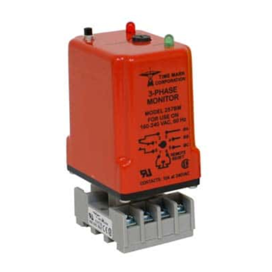
3 PHASE MONITORS
3 PHASE MONITOR
Detects Phase Loss, Low Voltage, Phase Reversal
50Hz, 60Hz, and 400Hz Models
Automatic or Manual Reset
DESCRIPTION
The Model 257 continuously monitors 3-phase power lines for
abnormal conditions. When properly adjusted, the Model 257
will detect phase loss on a loaded motor even when regenerated
voltage is present. This device consists of a solid-state voltage
and phase-angle sensing circuit, driving an electro-mechanical
relay. When correct voltage and phase rotation are applied, the
internal relay will energize. A fault condition will de-energize the
relay. When the fault is corrected, the monitor will automatically
reset. (A manual version is also available)
The Model 257 does not require a neutral connection and can
be used with Wye or Delta
systems. Voltage ranges are
sufficiently wide to allow for
proper adjustment to existing
conditions. Both TRIP and
NORM condition indicators are
provided to aid in adjustment
and system trouble-shooting.
SPECIFICATIONS MODEL 257
AUTO Reset
B257B
257B
Manual Reset
B257BM
257BM
Nominal AC Voltage
120VAC
208/240VAC
Phase-to-Phase
Case Color
Gray
Red
85-
160-
Adjustment Range
120VAC
240VAC
Frequency
60Hz
60Hz
Power Consumption
1.4W
2.4W
Transient Protection
Repeat Accuracy
Response Time
Dead Band
Output Contacts
Expected Relay Life
Operating Temp.
Humidity Tolerance
Enclosure Material
Mounting
Weight
Agency Approvals
(1) The 380V and 480V versions must be used with a UL Recognized 600Vac socket
(3) To Be Installed on the load side of branch circuit protection rated 10A.
**Order 8-Pin Socket Number 51X120 (UL Listing E126447)
Smart Socket Available for 480 to 635Vac Circuits
DIMENSIONS
All Dimensions In Inches
Div. Morlan & Associates, Inc.
4970 Scioto Darby Rd. Hilliard, Ohio 43026
3 PHASE MONITOR
Typical Application
A257B
EX257B
B257B-400
A257BM
WX257BM
B257BM-400 257BM-400
480VAC
380VAC
120VAC
Yellow
Yellow
Gray
380-
300-
85-120VAC
480VAC
400VAC
60Hz
50Hz
400Hz
3.7W
3.0W
1.4W
2500VAC for 10msec
+0.1% of set point (fixed conditions)
50msec (set or reset)
Approximately 2%
SPDT 10 Amps at 240VAC
Mechanical: 10 Million Operations
Electrical: 100,000 Operations at rated load
-20°F to +131°F
0-97% w/o condensation
Dust Cover: ABS Plastic
Header: Nylon
8-Pin Socket (**Sold separately)
5 ounces
UL Recognized* and CSA Certified
*Conditions of acceptability:
(2) For use in a Pollution Degree 2 Environment
WWW.FLEX-CORE.COM
sales@flex-core.com
®
E60400
INSTALLATION
Mount the 8-pin socket in a suitable enclosure. A NEMA-1 rated
enclosure, designed for socket-mounted relays is available
upon request. Connect 3-phase power to terminals 3, 4, and 5
on the socket. Phase rotation should be verified. Connect the
load control wiring to the appropriate terminals on the socket:
Motor Control Application ...............Use terminals 1 and 8
Phase Loss Alarm Applications ......Use terminals 1 and 2
Insert the Model 257 into the socket and apply power. If the
contact does not transfer (green light ON), check that all
phases are present, and of the correct voltage. If power is
correct, rotate the level adjustment counter-clockwise. If the
contact still does not transfer, remove power and reverse two of
the three phase wires at the socket (phase rotation reversed).
Re-apply power. The contact should transfer to provide a signal
path between pins 1 and 8.
ADJUSTMENT SETTING
The following procedure will allow the Model 257 to be adjusted
to achieve a trip point just below the nominal phase-to-phase
voltage, where the unit is applied.
Rotate the adjustment control fully clockwise, or until the red
(TRIP) indicator illuminates. Slowly rotate the adjustment
control in a counter-clockwise direction, just until the green
257B-400
(NORM) indicator illuminates. At this point, the Model 257 is
208/240VAC
the most sensitive to irregular power line conditions. If nuisance
tripping occurs, turn the control slightly further counter-
Red
clockwise. A more accurate setting will require the use of a
160-240VAC
3-phase variac to lower the voltage to an exact measurable
400Hz
2.4W
setting. A factory set version of all models and voltage ranges
are available. (Consult factory for details.)
TROUBLESHOOTING
Should the Model 257 fail to operate properly, check that all
three voltages are present, and are of the correct voltage
level and phase rotation. Check all fuses and verify that all
wiring connections are correct. If problems persist, consult the
factory for assistance.
MANUAL RESET VERSIONS
If you do not wish to use the external reset switch on the
manual reset version, you must jumper pins 6 and 7. Refer to
the manual reset 8-pin diagram.
PIN DESIGNATIONS
2
3
1
4
8
5
7 6
Automatic Reset
161
MODEL
OA
2 3
OB
1
4
8
5
OC
7 6
REMOTE
RESET
Manual Reset
PHONE (614) 889-6152
TECH. ASSISTANCE (614) 876-8308
FAX # (614) 876-8538
257
OA
OB
OC
Advertisement
Table of Contents

Summary of Contents for FLEX-CORE 257
- Page 1 Phase Loss Alarm Applications ..Use terminals 1 and 2 relay. When the fault is corrected, the monitor will automatically Insert the Model 257 into the socket and apply power. If the reset. (A manual version is also available) contact does not transfer (green light ON), check that all...
- Page 2 520Vac the Smart Socket limits the voltage potential so that it the Smart Socket limits the voltage potential so that it never 257B never rises above 395Vac. rises above 390Vac. WWW.FLEX-CORE.COM PHONE (614) 889-6152 sales@flex-core.com TECH. ASSISTANCE (614) 876-8308 Div. Morlan & Associates, Inc.
Need help?
Do you have a question about the 257 and is the answer not in the manual?
Questions and answers