
Subscribe to Our Youtube Channel
Summary of Contents for AUTOTERM AT0041
- Page 1 MARINE FUEL KIT User’s manual Manufacturer: AUTOTERM LLC Paleju 72, Marupe, Latvia, LV-2167 Warranty Department warranty@autoterm.com Technical Support service@autoterm.com www.autoterm.com v10.2021...
-
Page 2: Table Of Contents
CONTENTS INTRODUCTION ....................................3 SAFETY INSTRUCTIONS ..................................4 LIABILITY ......................................5 GENERAL INFORMATION ................................. 5 GENERAL FUEL SYSTEM INSTALLATION ............................6 FUEL SUCTION HOSE INSTALLATION............................6 ADDITIONAL FUEL TANK INSTALLATION ............................8 INSTALLATION OF THE FUEL PUMP AND FUEL LINE ........................8 MARINE FUEL KIT INSTALLATION .............................. -
Page 3: Introduction
INTRODUCTION Dear Customer! Thank you for choosing AUTOTERM Marine fuel kit! We are doing everything to make this product meet your requirements, so its quality satisfies every customer. This manual is intended for organizations that specialize in installation and maintenance of heaters AUTOTERM AIR, AUTOTERM FLOW and users of the product after installation. -
Page 4: Safety Instructions
- For safety reasons, contact the service shop to troubleshoot the heater if it fails to launch two times in a row. - In case of faults in the operation of the product, contact specialized repair organizations authorized by AUTOTERM. -
Page 5: Liability
GENERAL INFORMATION The AUTOTERM Marine fuel kit is designed to be used only with AUTOTERM AIR and AUTOTERM FLOW heaters. This fuel kit meets the requirements of ISO 7840 – MARINE FUEL A1 standard. It applies to hoses for small craft with permanently installed fuel systems. -
Page 6: General Fuel System Installation
GENERAL FUEL SYSTEM INSTALLATION Do not operate the heater using biofuel. Use only diesel fuel standard EN590 for diesel operated heaters and gasoline EN 228 for gasoline operated heaters, depending on the ambient temperature. Act as instructed on Fig.1 and Fig.5 to install the fuel system. The fuel pump and the fuel supply line must be protected from heating. - Page 7 Heater Figure 1 - Connection of fuel supply to the heater with fuel suction hose Fuel is taken directly from the fuel tank of the vessel or an additional tank. Drill a hole Ø16mm in the fuel tank to install a fuel suction hose. When drilling the hole in the fuel tank, follow safety precautions that should be observed when working with a transport, which is filled with fuel or explosive substance.
-
Page 8: Additional Fuel Tank Installation
Never install the suction hose on the side of the fuel tank. It must be installed on the top side of the fuel tank. ADDITIONAL FUEL TANK INSTALLATION Wall/hull of the vehicle/vessel Consider convenience of fuelling, when installing the fuel tank (Fig.3). Install the fuel tank in such a way that the amount of fuel and its potential leaks from the inlet, fuel suction nozzle Fuel tank or connections can be visually controlled. - Page 9 It is recommended to install the fuel pump close to the fuel tank (distance should not exceed 1 meter (see Fig.1 and Fig.5)) and below the low level of fuel in the fuel tank, but not lower than 70cm of the minimal fuel level (see Fig.5, point a)). But the height between the fuel pump and the heater cannot be greater than 1,5 meters (see Fig.5, point b)).
-
Page 10: Marine Fuel Kit Installation
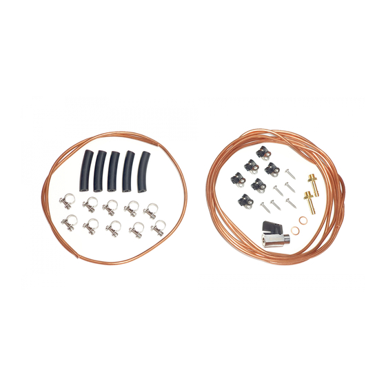
MARINE FUEL KIT INSTALLATION Figure 6 – Marine fuel kit assembly diagram 1 – Fuel tank 4 – Clamp 7 – Fitting 2 – Heater 5 – Shut off valve 8 – Sleeve 3 – Fuel pump 6 – Copper O-ring gasket 9 –... - Page 11 7. Connect 4m copper pipe piece (9) to the fuel pump outgoing side sleeve (8). 8. Fasten fuel pipe to the surface. It is preferable to lay the fuel supply line on a straight line and with a small inclination upwards in the direction of the heater.
Need help?
Do you have a question about the AT0041 and is the answer not in the manual?
Questions and answers