
Subscribe to Our Youtube Channel
Related Manuals for ToolKitRC MC8


Summary of Contents for ToolKitRC MC8
- Page 1 User Manual V1.0 2021.10 www.toolkitrc.com Toolkit RC Co., LTD @ToolkitRC 2021...
-
Page 2: Foreword
Foreword Thank you for purchasing the MC8 multi-checker. Please read through this manual carefully prior to operating the device. Manual icons Important Nomenclature Additional information For more information pertaining to the operation and maintenance of your device, please visit the following link: www.toolkitrc.com/mc8... -
Page 3: Safety Precautions
Safety precautions 1 , The operational voltage of the MC8 is between DC 7.0V and 35.0V. Ensure the polarity of the power source is not reversed prior to use. 2 , Do not operate under extreme heat, humidity, flammable and explosive environments. -
Page 4: Table Of Contents
Signal measurement ......... 10 1,PWM Signal measurement ......10 2,PPM signal measurement......11 3,SBUS Signal measurement ......12 Signal output............13 1,PWM Signal output ........13 2,PPM Signal output ........15 3,SBUS signal output........16 USB charging ............17 Calibration ............17 @ToolkitRC 2021... - Page 5 Product overview The MC8 is a compact multi-checker designed for every hobbyist. Featuring a bright, color IPS display, it is accurate to 5mV. Measures and balances LiPo, LiHV, LiFe and Lion batteries. Wide voltage input DC 7.0-35.0V. Supports Main/Balance/Signal port power inputs.
- Page 6 Layout IPS Display Signal port Main input Balance port Front Output slider Metal roller USB-C port USB-A port Rear @ToolkitRC 2021...
-
Page 7: First Use
First use 1,Connect the battery to the MC8’s balance port, or connect 5.0-35.0V voltage to the XT60 input port of the MC8. 2,The screen shows the boot logo for 0.5 seconds 3. After the boot is completed, the screen enters the main interface and displays as follows: 4. -
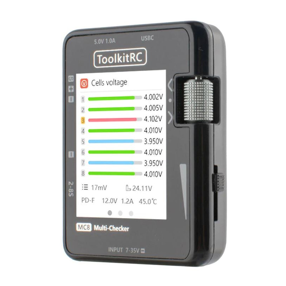
Page 8: Voltage Test
Voltage test 1,Voltage display and balance (individual cells) Connect the balance port of the battery to the MC8. After the device powers on, the main page shows the voltage of each individual cell- as shown below: The colored bars show the voltage of the battery graphically. -
Page 9: 2,Battery Pack Total Voltage
2,Battery pack total voltage Connect the battery lead to the main XT60 port on the MC8 to display the total voltage of the battery pack, as shown below. =================================== 1, The MC8 displays the total voltage of all battery chemistries operating within the input limits . -
Page 10: Signal Measurement
1500:Current PWM pulse width 20ms/5Hz : Current cycle and frequency of PWM signal. =================================== 1 , When using the signal measurement function. The signal port, balance port, and main input port can all supply power to the MC8. =================================== @ToolkitRC 2021... -
Page 11: 2,Ppm Signal Measurement
2,PPM signal measurement Under PWM signal measurement mode, press down on the scroller and scroll right until PPM is shown. Then the PPM signal can be measured, as shown below. @ToolkitRC 2021... -
Page 12: 3,Sbus Signal Measurement
,SBUS Signal measurement Under PWM signal measurement mode, press down on the scroller and scroll right until SBUS is shown. Then the SBUS signal can be measured, as shown below. @ToolkitRC 2021... -
Page 13: Signal Output
Signal output 1,PWM Signal output With the MC8 powered on, scroll right twice on the roller to enter Output mode. Press down on the scroller for 2 seconds to enter the signal output mode, as shown below. UI Description Mode:Signal output mode- can be changed between manual and 3 automatic modes of varying speeds. - Page 14 1 , When the cycle is set to less than 2ms, the maximum width will not exceed the cycle value. 2,The channel output slider is safety protected. There will be no signal output until the slider is returned to its minimum position first. =================================== @ToolkitRC 2021...
-
Page 15: 2,Ppm Signal Output
1 , The throttle channel can only be controlled using the signal from the output slider; the value cannot be changed using the roller for safety reasons. 2,Ensure the output slider is at its lowest point prior to performing any tests. =================================== @ToolkitRC 2021... -
Page 16: 3,Sbus Signal Output
1 , When the cycle is set to less than 2ms, the maximum width will not exceed the cycle value. 2,The channel output slider is safety protected. There will be no signal output until the slider is returned to its minimum position first. =================================== @ToolkitRC 2021... -
Page 17: Usb Charging
When any individual cell reaches 3.0V or below, the USB output will stop- preventing battery damage. =================================== Calibration Press and hold the roller while powering on the MC8 to enter calibration mode, as shown below: @ToolkitRC 2021... - Page 18 ADC: Original value of the selected option prior to calib Exit: Exit calibration mode Save: Save calibration data Defau.: Return to default settings =================================== 1,Only use multimeters with 0.001V accuracy to perform calibrations. If the multimeter is not accurate enough, do not perform calibration. =================================== @ToolkitRC 2021...
- Page 19 PD3.0 QC3.0 AFC SCP FCP 500-2500us @20-400Hz Measure 880-2200us*8CH @20-50Hz ment 880-2200us *16CH SBUS @20-100Hz 1000-2000us @20-1000Hz Output 880-2200us*8CH @50Hz SBUS 880-2200us *16CH @74Hz Size 68mm*50mm*15mm Product Weight Size 76mm*60mm*30mm Package Weight 100g IPS 2.0 inch 240*240 resolution @ToolkitRC 2021...
Need help?
Do you have a question about the MC8 and is the answer not in the manual?
Questions and answers
здравствуйте русского языка нету ?