
Subscribe to Our Youtube Channel
Related Manuals for Athena 1470-HE EVO


Summary of Contents for Athena 1470-HE EVO
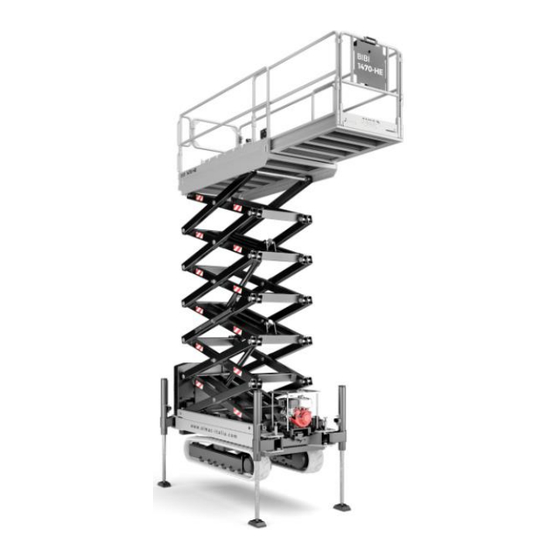
- Page 1 ATHENA 1470-HE EVO Translation of original instructions Prior to commissioning the machine read carefully this Use and Maintenance Manual Note: table of contents at the end of the manual Edition Date 04/07/2017...
-
Page 2: General Information
1.2 Details of Manual • Instruction manual for Elevating work platform • Model Athena 1470-HE EVO Note: Some of the photos and illustrations may not refer specifically to the version of the machine in your possession, but provide indications concerning the purpose for which they have been included. - Page 3 PAGE 1.3 Ownership of the information This document contains confidential information. All rights reserved. This manual may be neither partially nor totally duplicated without the prior written authorization of ALMAC s.r.l. This document may only be used by the customer to whom the manual has been supplied along with the machine, and only for the purpose of use and maintenance of the machine to which the manual refers.
- Page 4 PAGE 1.5 MEWP identification data The machine named Athena 1470-HE EVO is defined according to technical standards in force (ref. EN UNI EN 280:2015), as: Mobile Elevating Work Platform (MEWP), belonging to group A, type 3 (point 1.4-EN 280) Meanings:...
- Page 5 PAGE ASPAC GROUP ELEVATING WORK PLATFORM MANUFACTURER ALMAC s.r.l. SERIAL ALM-000631 MEWP MODEL NUMBER YEAR OF UNLADEN WEIGHT 2018 WITH TRACKS MANUFACTURE DATE OF TEST 250 kg RATED LOAD INC. 2 OCCUPANT & TOOLS 40 daN MAX ALLOWABLE SIDE FORCE 12,5 m/s MAX WIND SPEED 5,99 mt...
- Page 6 PAGE 1.6 Performance Below are the configurations that the mobile elevating work platform can have during operation and transport.
- Page 7 PAGE...
- Page 8 PAGE Dismantle the railings only for special transport situations; before commissioning, the machine must be reconfigured by skilled and authorised personnel, according to the certified diagram, following the manufacturer's instructions Characteristic dimensions Chassis length 2,16 Machine length 3,18 With stabilisers open Length of retracted work platform 2,62 Machine width...
- Page 9 PAGE Work area on stabilisers in wide position. Maximum inclination allowed: ± 0.5°...
- Page 10 PAGE Characteristic dimensions Maximum work height 14,22 Min height of floor surface 12,22 Maximum work space in width 2,08 Maximum work space in length 5,02 Useful work distance in width Useful work distance in length Useful work distance in length 1,70 Distance between the stabilisers in width Maximum height of track from ground...
- Page 11 PAGE Work area on stabilisers in narrow position. Maximum inclination allowed: ± 0.5° 2080 5020 1370 4000 1680 1000 3230 1130 3480 Warning! It is sufficient to position a single stabiliser in the narrow position to have the work area on stabilisers in the narrow position.
- Page 12 PAGE Work area on tracks. Travel not allowed Maximum inclination allowed: ± 2° 5020...
- Page 13 PAGE Work area on tracks. Travel allowed at reduced speed. Maximum inclination allowed: ± 2° 5020 Technical data Capacity of work platform Number of operators on work platform Lifting time (with 300Kg on the platform) Lowering time Hydraulic side-shift pressure 195 ±...
- Page 14 PAGE Technical data Maximum travelling speed km/h Overall weight 3480 Max wind force 12.5 Starter battery voltage and capacity V/Ah 12/50 Weight of starter battery Sound power LwA Sound level at operator position Lp (indoor industrial 84.5 ± 2.6 environment) Sound level at operator position Lp (outdoor environment on 79.5 ±...
- Page 15 PAGE Electronic tilt control Electronic anti-shearing protection Engine specifications Z602-E3B TIER 4 Dry weight 60 kg Type of engine 4 TIMES LIQUID COOLING - DIESEL – Swept volume 599 cm Net power 12.5 kW @ 3600 rpm Net torque 38 Nm @ 2500 rpm Q.ty engine oil 3 Lt Fuel tank capacity...
-
Page 16: Warranty
PAGE 1.7 CE Declaration of Conformity See facsimile of CE declaration of conformity enclosed with this manual. The machine described in this manual complies with the following standards: • Directive 2006/42/EC Machinery Directive that amends Directive – 95/16/EC • Legislative Decree D.Lgs 17/2010 Implementation of Machinery Directive –... - Page 17 PAGE 1.8.1 Request for interventions during warranty period and formalities ALMAC S.r.l. must be notified of requests for spare parts or technical interventions under guarantee as soon as a defect is discovered. Always indicate the type of machine and its serial number when requesting spare parts under guarantee or technical interventions under guarantee.
- Page 18 PAGE 1.10 Use of the manual Note: Keep this manual in an accessible place known to all users (operators and maintenance workers). Note: This manual must be kept in a protected place inside the compartment provided on the work platform so that it can be easily accessed for consultation throughout the entire technical life of the machine.
- Page 19 PAGE 1.11 Intended use and improper uses 1.11.1 Intended use The machine described in this manual is a self-propelled elevating work platform designed to lift personnel and equipment to perform the following jobs: • professional gardening and general work • installation of systems and equipment •...
- Page 20 PAGE Attention: NEVER exceed the machine's established maximum capacity. Attention: It is FORBIDDEN to transport large slabs or materials since this could increase wind resistance to a considerable extent and cause the machine to tip over. Attention: It is FORBIDDEN to apply horizontal loads to the platform when the machine is moving (e.g.
- Page 21 PAGE 1.11.2 Improper uses Any other use not specifically indicated in 1.11.1 Intended use. • The improper uses established for this MEWP include lifting and lowering persons to/from different storeys within space (typical use of elevators). • It is also forbidden to drive the platform to the ground using the mobile push-button panel with an operator on the work platform.
-
Page 22: Safety Information
PAGE 2 SAFETY INFORMATION 2.1 Notification of commissioning and routine inspections The work equipment indicated in Annex VII to Legislative decree D.Lgs 81/2008 and successive amendments must be subjected to REGISTRATION and ROUTINE INSPECTIONS by the competent authorities, i.e. INAIL, the National Institute for Insurance Against Industrial Accidents (former ISPESL, Higher Institute for Prevention in the Workplace), the Local Health Authority and other public and private bodies established by the criteria laid down in Ministerial decree DM... - Page 23 PAGE • psychological equilibrium, absence of depression or stress Operators who use the machine for professional purposes must undergo health surveillance as required by Legislative decree D.Lgs 81/2008 and successive amendments, particularly with regard to alcohol addiction and alcohol concentration tests. *The law that currently governs health control and surveillance of workers is the Provision of the State-Regions Permanent Conference of 16 March 2006.
- Page 24 PAGE 2.3 Warnings The following sign plates are affixed to the machine: • Identification • Instructions • Command/prohibition sign plates • Caution • Danger 2.3.1 Plates indicating instructions, obligations, dangers, prohibitions and warnings...
- Page 25 PAGE Sticker with maximum inclinations of the ground dangerous for the risk of tipping over and slipping, travelling with the machine completely lowered Maximum inclination of the ground: Front inclination of the ground: The maximum front inclination of the • ground to stay safe is 25°.
- Page 26 PAGE Sticker with maximum inclinations of the ground dangerous for the risk of slipping and tipping over, with the machine on the stabilisers. The suggested maximum inclination of the ground under each stabiliser is 10°. Note: The inclinations listed on the plate above refer to those LIMITS that cannot be exceeded with the machine.
- Page 27 PAGE...
- Page 28 PAGE...
- Page 29 PAGE Note: The plates are affixed to the machine for the purpose of helping the operator and/or warning him of the risks to which he may be exposed when he uses the machine. In no way does the information on the plates substitute this Manual, which is the only reference document containing complete information.
- Page 30 PAGE 2.3.2 Meanings of the sign pictograms Warning / Danger. This symbol means that you must take care or that danger is present. Failure to comply with this alert indication could cause damage to the machine, the operator or exposed persons.
- Page 31 PAGE 2.4 Provisions and prohibitions • Read this manual carefully before starting, using, servicing or performing other operations on the machine. • The MEWP must always be kept in perfect conditions by following the maintenance program described in the Maintenance Chapter. •...
- Page 32 PAGE • USE OF THE PLATFORM ALWAYS REQUIRES 2 OPERATORS, ONE OF WHOM ON THE GROUND and able to perform the emergency operations described in this Manual. • The platform must not be used if there is insufficient light, since it is not fitted with its own lights.
- Page 33 PAGE 2) Lifting the platform using a CE certified beam (not included) and using hooks and steel steel ropes hooked to the holes marked with signs (see photo below). A T T E N T IO N ! T h e h an d rails sh all b e fo ld e d d o w n 2980K g M A X N °4 h ig h stre n g th e ye b o lts M 1 2 N °4 h ig h stre n g th e ye b o lts M 1 2...
- Page 34 PAGE Warning: Do not tighten the fixing belts too much, so as not to damage the eye- bolts.
- Page 35 PAGE 2.6 Checks on the machine before each use • Visually check under and around the machine to make sure that there are no oil or fuel leaks. If leaks are discovered, follow the MAINTENANCE instructions. • Make sure that there is no hydraulic oil leaking from the hoses and from the other components (cylinders, distributors, fittings, etc.).
- Page 36 PAGE 2.7 General safety indications on the use of the platform The instructions given below must be followed. • It is forbidden to use ladders or other structures in the basket to increase the height of the machine. • It is forbidden to place structures inside the basket to increase the surface area exposed to the wind.
- Page 37 PAGE 2.8 Safety indications on the use of the travel function The instructions given below must be followed. • Make sure movements are done on flat, sturdy ground. To do this, use the spirit level located on the work platform. •...
- Page 38 PAGE • Do not drive along the edge of slopes or over uneven ground with one track horizontal and the other slanting or partially raised (>10°) as this will damage the tracks. ALWAYS PROCEED WITH THE TRACK SHOES RESTING ON THE SAME HORIZONTAL PLANE.
- Page 39 PAGE NO ICE! NO SAND! NO DUST OR SMOOTH SURFACES! Attention: during movement with ELECTRICAL POWER, be careful of the connection cable in order to avoid dangerously crushing the cable itself! 2.9 Mandatory safety indications to follow before lifting the work platform above the transport height with stabilisation on the tracked chassis.
- Page 40 PAGE The ring gear of the wheel drive units and the track tensioner wheels must all be resting on the ground. If even one of them is not in contact with the ground, the stabiliser area will be reduced and, consequently, the platform will be unstable and there will be the risk of overturning.
- Page 41 PAGE Also make sure that none of the stabiliser cylinders has reached its maximum extension. An automatic system allows for the platform to operate only if all the stabilisers are on the ground and none of them is completely extended. Moreover, an automatic system allows for the platform to operate only if all the pins are completely inserted in their housings.
- Page 42 PAGE Note: The platform is fitted with a crush-preventing system (ref. Point “ ” 5.4.4 EN 280), which gets enabled when the platform lowers and temporarily blocks it to allow the operator to make sure there are no bystanders near the machine.
- Page 43 PAGE • Operate the ground movement emergency button; make sure that the engine turns off (both the internal combustion engine and the electrical engine) and that no functions are allowed. Release the mushroom-shaped button after this test. • Operate the warning buzzer and make sure it works. •...
- Page 44 PAGE THE MANUFACTURER IS RELIEVED FROM ALL LIABILITY FOR ACCIDENTS OR FAULTS DUE TO FAILURE TO COMPLY WITH THE RECOMMENDATIONS AND SAFETY REGULATIONS. • Proceed with maintenance operations only after turning off the machine and deactivating the battery disconnect switch. •...
- Page 45 PAGE The photo above shows how the locking system of the extensible structure must be positioned during maintenance work. By means of the "ground controls", it is possible to lift the work platform until it is possible to place the two locking brackets vertically and aligned with the pins below. Subsequently lower the work platform until the brackets are locked in the relative pins.
- Page 46 PAGE • Make sure there are no fluids under pressure before disassembling unions or pipes: oil spattering out under pressure can cause serious injuries. Immediately call a physician if injuries occur or the fluid from pipes is accidentally ingested. Remember that fluid seeping from a very tiny hole can be almost invisible but possess sufficient force to penetrate under the skin.
-
Page 47: Personal Protection Equipment
PAGE Attention: This device is not to be considered a fall protection system, it is only used to prevent the fall. PERSONAL PROTECTION EQUIPMENT... -
Page 48: Description Of The Machine
PAGE 3 DESCRIPTION OF THE MACHINE 3.1 Structure of the equipment This section describes the main components of the machine and their functions. 3.1.1 Work platform assembly 3.1.2 Scissor assembly 3.1.3 Tank and chassis assembly... - Page 49 PAGE 3.1.1 Work platform assembly 1. Control push-button panel 2. Control console emergency button (console) 3. Glove box 4. Work platform 5. Spirit level 7. Device to access the work platform 6. Socket on work platform...
- Page 50 PAGE 8. Extendible basket pedal...
- Page 51 PAGE 3.1.2 Scissor assembly 9. Lifting cylinders 10. Seal solenoid valve on upper lifting cylinder SV19 11. Seal solenoid valve on lower lifting 12. Additional seal solenoid valve on both lifting cylinders SV21 cylinder SV18...
- Page 52 PAGE 13. Pressure transducer of the upper 14. Pressure transducers to control the load in the basket cylinder to control solenoid valve SV19 15. Scissor angle sensor...
- Page 53 PAGE 3.1.3 Tank assembly 16. Ladder to access the platform 17. Main hydraulic unit 18. Main differential panel 19. Ground control panel 20. Flashing light 21. Ground control panel emergency button...
- Page 54 PAGE 22. ECU electronic control unit 23. Battery disconnect switch 24. Emergency descent device 25. Hydraulic oil tank...
-
Page 55: Engine Starter
PAGE 26. Discharge filter 27. Intake filters (in the tank) 28. Oil tank refill cap 29. Visual hydraulic oil level 30. Booster for management of third 31. Combustion engine starter travel speed battery... - Page 56 PAGE 32. Electrical engine (if present) 33. Inverter (if present) 34. Inverter differential panel 35. Frame angle sensor present) 36. Combustion engine 37. Fuel tank...
- Page 57 PAGE 38. Chassis and stabilisers...
- Page 58 PAGE 3.2 Control stations 3.2.1 Mobile control push-button panel (console) The platform is equipped with a mobile control push-button panel (console) which allows for normal operation on the work platform. The console can be located in the dedicated metal support attached to the railing of the platform or removed and held by the operator.
- Page 59 PAGE Attention: If the platform is transported on vehicles, always secure the support by means of the threaded knob. The push-button panel can also be disconnected from the spiral cable by unscrewing the ferrule indicated with A. Attention: Do not touch ferrule B; if ferrule B is turned, the wires inside the connector will be damaged.
- Page 60 PAGE Warning: For all operations that required lifting the work platform above the transport height, the console and the operator must be inside the platform itself.
- Page 61 PAGE Identification Function and Status Description of the function PLANARITY ALARM No alarm Indicator light FLASHING Loss of contact with ground alarm Inclination alarm TRAVEL ALLOWED Indicator light Travel not allowed Driving enabled WORK ENABLING Depending conditions: Machine off or with platform lifting not allowed or without controls in Indicator light general allowed...
- Page 62 PAGE Identification Function and Status Description of the function electrical engine. To turn on the electrical engine, it is necessary to turn selector 5 ON. The electrical engine works only if the plug under ladder has been connected to an external power source.
-
Page 63: Emergency Stop
PAGE Identification Function and Status Description of the function levelling 13 Selector switch Ascent / descent Emergency EMERGENCY STOP Button The central selector switch open - close is not active in this platform model 3.2.2 Ground control using the mobile push-button panel With the mobile control push-button panel, as well as allowing for the normal operation of the work platform, it is possible to temporarily remove and use the machine from the ground. - Page 64 PAGE During this operation, be careful not to come into contact with the platform tracks. Stay at a safe distance using the length of the spiral cable. Once the transport phase is over, place back the push-button in its original seat. 3.2.3 Ground controls The platform features a control console located on the chassis at the back of the machine.
-
Page 65: Engine On / Off
PAGE Identification Function and Status Description of the function Display of the hours of operation and machine status, with Display an indication of any alarms. PLATFORM UP / DOWN SELECTOR To control the upward movement of work platform, move 19 Selector switch selector UP To control the downward movement of the work platform, move the... - Page 66 PAGE Identification Function and Status Description of the function To turn off the engine, move the selector to the OFF position Emergency EMERGENCY STOP Button MACHINE ON / OFF SELECT CONTROL STATION CENTRAL position Machine off LH position Ground controls selection (it is only (operator on the possible to turn the engine on/off Key selector...
- Page 67 PAGE 3.3 Storage compartment On the platform, under the control console, there is a compartment, which can be opened by hand. It contains: • This Use and Maintenance Manual • The spare parts catalogue • Wiring diagrams • Hydraulic diagrams •...
- Page 68 PAGE 3.4 Platform operation safety devices Attention: Periodically verify that the safety devices are operating correctly. During work, the operator must be able to assess, recognize and avoid all dangers and must immediately inform the persons in charge of any faults in the safety devices so that they can be inspected and restored to their original conditions of safety and reliability DO NOT TAMPER WITH AND DO NOT CHANGE THE CALIBRATION OF ANY OF...
- Page 69 PAGE 3.4.2 Work platform height control device On the scissor frame there is a Can Bus angle sensor that constantly communicates the inclination measured to the electronic control unit. The angle sensor is redundant (thus consisting of two separate sensors) and the Y inclination axis of the scissor frame is monitored (longitudinal) The signals of the two sensors are constantly compared with each other to assess their consistency.
- Page 70 PAGE 3.4.3 Load limiting device The machine is equipped with a work platform that, once extended, has a surface area greater than 1 m². For this reason, on the lower cylinder there are two pressure transducers which, with the angle sensors of the frame and of the scissors, make up a system able to detect whether the load on the work platform exceeds the nominal load by 20%.
- Page 71 PAGE 3.5 Hydraulic system safety devices 3.5.1 Hydraulic pressure limiting devices The hydraulic system of the platform features special general maximum pressure valves (R-Q) in order to limit the pressures relating to the operation of the machine, preserving the integrity of the various components. These valves need no adjustments since they are calibrated by ALMAC S.r.l.
- Page 72 PAGE 1. Maximum system pressure valve (R) : set to 200 ± 5 bar 2. Maximum system pressure valve (Q) : set to 200 ± 5 bar 3. Maximum lifting pressure valve (P) : set to 160 ± 5 bar (in the version 1470 HE it is set to 195bar) Warning: modifications to the positions of the maximum pressure valves without authorization from ALMAC S.r.l.
- Page 73 PAGE ATTENTION: After performing any manual operations on the A-B-C-N-O valves, their factory settings must be restored or machine safety will be compromised, with the risk of the platform potentially overturning. 3.5.3 Hydraulic failure safety devices The hydraulic system of the lifting circuit, in the event that there is an accidental fault in the hydraulic piping that feeds the lifting cylinders of the work platform, features three one-way valves, normally closed (1), electrically driven and connected directly to the cylinder, which prevents the uncontrolled...
- Page 74 PAGE...
- Page 75 PAGE UPPER CYLINDER SV19 LOWER CYLINDER SV18 SV21 Solo nella 1470 20cc Proceed as described below to restore the machine to normal operating conditions: 1. Repair the damaged hydraulic hose and/or connections 2. Fill and bleed the hydraulic circuit 3. Lift the platform to its maximum height If one of the hydraulic hoses that supply the stabiliser cylinders malfunctions and the inclination suddenly changes, dedicated CHECK VALVES prevent the machine from moving suddenly (ref.Point 5.10.2 EN280).
- Page 76 PAGE...
- Page 77 PAGE...
- Page 78 PAGE 3.6 Blackout safety devices 3.6.1 230V external power source On the work platform there is a power socket to supply the power tools required during work. For safety reasons, a device is installed so as to cut-out the electricity supply in case of over-voltage and "differential circuit breaker" dispersions (1).
- Page 79 PAGE 3.6.2 220V inverter (optional) If the machine is equipped with a 220V inverter to power the outlet on the work platform, the following safety devices will also be present: 1) Insulation control device between the cables that go from the inverter to the outlet on the work platform and the machine frame (Sentinel) 2) Trip coil (triggered in the event of an alarm from the sentinel) 3) Circuit breaker...
- Page 80 PAGE...
-
Page 81: Preliminary Operations
PAGE 4 Instructions for use 4.1 Preliminary operations 4.1.1 Suitability of the soil To assess whether the ground is fit to bear the machine, it is extremely important to ensure that the ground surface does not allow the machine to slip once it has been stopped for work. - Page 82 PAGE Maximum inclinations on stabilisers On stabilisers, the platform can be levelled and exceed inclinations up to 21° on the lateral and up to 12° on the longitudinal. The inclination of the ground under the stabiliser feet, however, must not exceed 10°.
- Page 83 PAGE 4.1.1.1 Mandatory safety indications to follow before lifting the work platform above the transport height with stabilisation on the tracked chassis. The instructions given below must be followed. Lift the work platform only after making sure, both visually and by moving inside the work platform, that all 4 ends of the tracks rest on the ground.
- Page 84 PAGE Also make sure that none of the stabiliser cylinders has reached its maximum extension. An automatic system allows for the platform to operate only if all the stabilisers are on the ground and none of them is completely extended. Moreover, an automatic system allows for the platform to operate only if all the pins are completely inserted in their housings.
- Page 85 PAGE 4.1.2 Action of the wind It is forbidden to use the machine if the wind speed exceeds 12.5 m/s. The following chart describes the consequences of different wind speeds (Beaufort scale). Scale of the Italian Hydrographic Service Beaufort International Scale Effects Corresponding speed N°...
- Page 86 PAGE Danger: The platform must never be used when wind speed corresponds to a value greater than 6 of the Beaufort scale. Work must be performed with the utmost warning with wind speeds between 4 and 6 of the scale. 4.1.3 Access to the work platform The work platform must only be accessed with the platform completely LOWERED.
- Page 87 PAGE Attention: IT IS FORBIDDEN to block the gate in such a way as to keep access to the platform open.
- Page 88 PAGE 4.1.4 Checking the fuel level Before turning on the engine and/or starting a work shift, it is advisable to check the fuel level. The fuel level is visible in the ground control area (1). There is also a reserve sensor (2). If the fuel level is too low, the machine will emit an acoustic signal, the FUEL alarm will appear on the display and after 15 seconds the engine will turn off to avoid emptying the fuel system completely.
- Page 89 PAGE 4.1.5 Checking the oil level in the engine Check the engine oil level before starting it, or when more than 5 minutes have gone by after stopping it. Pull out the oil level indicator, clean it by wiping it and reinsert it. Pull the oil level indicator out again and check.
- Page 90 PAGE 4.1.6 Work platform extension The work platform is provided with a driven mechanism that enables to further extend the work area so as to reach more distant parts. To extend the work platform, it is necessary to: 1. Push the unlocking pedal (A) 2.
- Page 91 PAGE Warning: while descending from the working position, pay warning to possible obstacles beneath the work platform to prevent the platform from overturning or being damaged!
- Page 92 PAGE 4.1.7 Folding the railings The platform is provided with folding railings which facilitate the transport and the passage inside vehicles. To perform the folding, unlock the pins located on every railing according to a pre-determine sequence. • Extend the work platform according to the instructions given in sect.
- Page 93 PAGE • Open access gate according to the picture • Unlock the fastenings of the railing work platform • Fold the railing according to the figure • Unlock the fastenings of the – railing work platform • Fold the railing according to the figure •...
- Page 94 PAGE • Should it be required to transport the machine, it is necessary close expandable part up to the "T" lock. Unlocking the railing fastenings To unlock the railing fastenings, it is necessary to: 1) Turn the safety catch (A) of the locking pin (B) and then pull it from its seat 2) Remove the safety screw (C) 3) Once you have extracted all fastenings of the railings, is possible to fold it according to the instructions in the previous pages...
- Page 95 PAGE Before stepping on the platform, it is absolutely mandatory to put all the railings back in the vertical position and secure them as shown in the figure.
- Page 96 PAGE 4.2 Machine operation 4.2.1 Starting the internal combustion engine To start the internal combustion engine and the hydraulic pumps, use the ignition key on the ground controls. The key-switch functions are: • (CENTRAL): Machine off - electrical system not powered •...
- Page 97 PAGE 4.2.2 Starting the current source During operation with the INTERNAL COMBUSTION ENGINE, it is possible to turn the selector (6) to the OUT 220V position. In this way, it will be possible to use the 220V power in the outlet on the work platform (only for machines with inverter).
- Page 98 PAGE • Use an extension power cord with an appropriate section depending on its length Warning: the connection to a network that does not meet the requirements of the electrical engine may cause serious damage to some of the components of the machine.
- Page 99 PAGE 4.2.4 Travel controls The controls used for the movement of the platform are represented by 2 joysticks (10-11) located on the control panel. (see photo below). Each lever controls the respective track (right lever right track, left lever left →...
- Page 100 PAGE Left turn Rotation on itself towards the right (counter-rotation) Rotation on itself towards the left (counter-rotation) Travel is enabled or disabled depending on the status of the travel approval light located on the control panel. It provides the following information:...
- Page 101 PAGE • On: travel allowed • Off: travel not allowed WARNING: If you must drive up a slope, do not change direction when the ground changes from flat to sloping. If this is absolutely necessary, perform the manoeuvre gradually. It is forbidden to climb on the tracks to attempt any operation that is not allowed or to use the controls on the work platform.
- Page 102 PAGE It is forbidden to travel above the transport height in the following conditions: • Wet ground • Snowy and/or icy ground • Dry asphalt but covered with sand, gravel or other aggregates Warning: slipping hazard! 4.2.4.1 Travelling with the platform in the transport position Adjusting the speed: It is possible, using selector 8 on the push-button panel, to enable the second travel speed with the work platform in the transport position.
- Page 103 PAGE 4.2.4.2 Travelling with the work platform above the transport height With the platform raised above the transport height, the maximum travel speed is automatically limited to a maximum value of 0.4Km/h. Travel is allowed only up to a height of 4.5 m (floor surface). In this case too, if selector 8 is in hare mode, the left joystick is not active and the right joystick (11) controls both tracks.
- Page 104 PAGE 4.2.5 Machine stabilising controls The platform in question has two possible stabilisation areas. Narrow stabilisation (maximum height of floor surface 7.16m) 2080 5020 1370 4000 1680 1000 3230 1130 3480...
- Page 105 PAGE Wide stabilisation (maximum height of floor surface 12.22 m) 2080 5020 1370 4000 1700 1400 2830 1530 3080 An automatic system, by means of a limit switch and pressure transducers, allows for the platform to be lifted only if all the stabilisers are on the ground and none of them is completely extended.
- Page 106 PAGE The operations required to select the stabilisation area are the following: 3. Pull the locking lever upwards. 2. Turn the stabiliser outwards (wide stabilisation area) or inwards (narrow stabilisation area) 1. Release the lever once the correct position of the stabiliser has been reached.
- Page 107 PAGE 4.2.5.1 Automatic stabilisation To perform operations on surfaces which are not planar, but complying with the maximum slopes allowed, the machine comes with an "automatic stabilisation" system which is enabled while the "STABILISERS" lever (11) is activated, only when the platform is configured within the maximum transport height (< 2 m floor surface).
- Page 108 PAGE However, if a stabiliser reaches its maximum extension, it will not be possible to lift the work platform. It will then be necessary to keep the automatic destabilisation selected to bring the machine back to a lower stabiliser extension condition. IMPORTANT: to reduce the stabilisation time, it is recommended not to try to reach the maximum extension of the stabilisers but to perform the stabilisation procedure once only.
- Page 109 PAGE • Use the stabilisation control lever to operate the selected stabiliser in one direction or the other During this operation, if the platform reaches the value of 5° of inclination of the frame with respect to the ground, the manoeuvre is interrupted automatically.
- Page 110 PAGE WARNING: Risk of slipping and overturning, with the machine on the stabilisers. The suggested maximum inclination of the ground under each stabiliser is 10°. Carefully check the conditions of the ground before operating with the platform.
- Page 111 PAGE 4.2.6 Summary of the possible work configurations FRAME ± 2° ± 2° ± 0.5° INCLINATION HEIGHT OF Lower than the Higher than the Higher than the Higher than the WORK transport transport transport height transport height PLATFORM height height Allowed at Allowed but only TRAVEL...
- Page 112 PAGE 4.2.7 Lifting/descent of the work platform The work platform can be lifted by means of the dedicated selector on the control push-button panel. The lifting and descent speed are controlled by the electronic control unit (ECU). The platform descent can also be performed with the combustion engine off but the electrical panel ON.
- Page 113 PAGE 4.2.8 Manual warning buzzer Use the button on the push-button to operate the platform buzzer. It must be used whenever persons working or moving around the platform area must be warned that platform movements are in progress. Warning: The continuous use of this device reduces the battery charge. 4.3 Warnings for the operator by means of the indicator lights on the control push-button panels In general, the indicator lights of the push-button panel, as well as indicating...
- Page 114 PAGE Work platform in transport position, machine on tracks, lateral and longitudinal inclination of the frame lower than or equal to 2° Planarity alarm Travel allowed OK Work Overload alarm Acoustic alarm Work platform in transport position, machine on tracks, lateral and longitudinal inclination of the frame greater than 2°...
- Page 115 PAGE Work platform lifted more than 4.5 m floor surface, machine on tracks, lateral and longitudinal inclination of the frame lower than or equal to 2° Planarity alarm Travel allowed OK Work Overload alarm Acoustic alarm Work platform lifted more than 4.5 m floor surface, machine on tracks, lateral and longitudinal inclination of the frame greater than 2°...
- Page 116 PAGE Work platform in transport position, one, two or three stabilisers on the ground, lateral and longitudinal inclination of the frame greater than 0.5° Planarity alarm Travel allowed OK Work Overload alarm Acoustic alarm (The work platform cannot be lifted) Work platform in transport position, 4 stabilisers on the ground, lateral and longitudinal inclination of the frame greater than 0.5°...
- Page 117 PAGE inclination of the frame lower than or equal to 0.5° Stabiliser pin not inserted Planarity alarm Travel allowed OK Work Overload alarm Acoustic alarm (The work platform can descend only) Work platform raised, 3 stabilisers on the ground, lateral and longitudinal inclination of the frame lower than or equal to 0.5°...
- Page 118 PAGE 4.4 Messages and alarms on the hour counter The hour counter, placed next to the ladder, allows to display the machine status. This display also shows any errors and/or alarms that may occur. If there are no alarms present, the display will show the hours of work with the electrical engine and with the internal combustion engine: d = hours of operation with petrol or diesel engine E = hours of operation with electrical engine...
- Page 119 PAGE If there are no alarms at the moment but there were alarms previously (alarms caused by malfunctions that appear intermittently), the service symbol will appear on the display: The control unit can store up to 16 alarms which are shown by pressing the right button of the hour counter.
- Page 120 PAGE Starter battery voltage higher than 16V EPROM memory internal error CAN network communication error Frame angle sensor redundancy error Scissor angle sensor redundancy error Pressure transducer redundancy error No signal from the frame angle sensor 1 No signal from the scissor angle sensor 1 No signal from the pressure transducer 1 No signal from the frame angle sensor 2 No signal from the scissor angle sensor 2...
- Page 121 PAGE Compatibility error between the contacts NC and NO of the limit switch of the pin inserted in stabiliser 3 Compatibility error between the contacts NC and NO of the limit switch of narrow stabilisation of stabiliser 3 Compatibility error between the contacts NC and NO of the limit switch of the pin inserted in stabiliser 4 Compatibility error between the contacts NC and NO of the limit switch of narrow stabilisation of stabiliser 4...
- Page 122 PAGE 4.5 Stopping the machine 4.5.1 Normal stop During normal platform use, releasing the TRAVEL joysticks (10 and 11) stops the movement. Each track installed has a braking system that prevents the machine from moving unless hydraulic pressure is exercised to disengage it. Releasing the platform UP or DOWN (13) lever, under normal working conditions, stops the relative movement.
-
Page 123: Emergency Procedures
PAGE pressing the MUSHROOM-SHAPED button on the push-button, or the emergency button place on the GROUND CONTROLS (see figures below). 5 Emergency procedures 5.1 Emergency manual descent and/or lifting Following a failure in the electrical system or hydraulic circuit, the platform DESCENT manoeuvre can be performed from any height by means of the emergency control at ground level. - Page 124 PAGE Operate the manual pump (1) using the dedicated lever. When the platform starts to move down, it will be necessary to continue to operate the manual pump for a few seconds, whilst keeping the diverter knob pulled, and wait for the platform to have lowered completely. Warning: This control must be used only in an emergency, that is the failure of the hydraulic or electrical system or if it is not possible to bring the operator on the platform to the ground using the ground controls of the machine.
- Page 125 PAGE Press and hold the solenoid valves 6 and 7 on the hydraulic unit Operate the manual pump using the dedicated lever. Warning: This mechanism must only be used in an emergency, i.e. electrical or hydraulic failure. WARNING: during these operations it is necessary to keep well away from the scissors, paying attention to the limbs.
- Page 126 PAGE 5.3 Emergency movements from hydraulic block Warning: this operation must be performed only by qualified technicians trained by Almac Srl If the control unit is not working but it is possible to turn on the internal combustion engine or the electrical engine, then it will be possible to perform then movements of the machine directly from the hydraulic block.
- Page 127 PAGE Moving the machine (Forwards or backwards) IMPORTANT: It is not possible to move both tracks at the same time. If both proportional valves are completely closed, the engine will stop and this may damage the pumps. It is possible to move one track at a time only. 1) Completely turn the screw on solenoid valve EV17 (C) anti-clockwise 2) To move the right track, completely turn the screw of solenoid valve EV8 (B) clockwise.
-
Page 128: General Maintenance
PAGE 6 Maintenance 6.1 General maintenance The main maintenance interventions and the frequencies with which they must be carried out are given in the chart below. 6.1.1 Ordinary maintenance schedule table The checks and maintenance operations must be performed as indicated in the table below ORDINARY MAINTENANCE SCHEDULE TABLE 10 50 100 250 500 1500... - Page 129 PAGE A. Whenever the machine is D. monthly or every 100 hours G. annually or every 1500 hours used B. Daily or every 10 hours E. every two months or every H. after long periods of inactivity (30 days) 250 hours C.
- Page 130 PAGE 6.1.2 Checks before each use Prior to commissioning and before each use the machine must undergo the visual and functional checks given below. The instructions given below must be followed. VISUAL CHECK CHECK OPERATION • • Visually check under and around the With platform transport...
- Page 131 PAGE fully charged; a simple way to check is the platform lifted; this test is performed by turning on the internal combustion lifting the platform to a height that involves an engine, which must turn on easily. angle of the scissor frames of 20° with respect •...
- Page 132 PAGE button; make sure that the engine turns off (both the internal combustion engine and the electrical engine) and that no functions are allowed. Release the mushroom-shaped button after this test. • Operate the warning buzzer and make sure it works.
-
Page 133: Maintenance: Details
PAGE 6.2 Maintenance: Details The following points deal with the most significant specific cases 6.2.1 Checking and tightening screws, bolts, plug ring nuts The operation of the following components must be checked. If necessary, the parts must be tightened with the appropriate tools as indicated in the charts on the following pages. - Page 134 PAGE 6.2.2 Visual and structural inspection Visually check the following points according to the schedule indicated in the general chart. Immediately inform a maintenance technician if faults are discovered. • Integrity of the railings of the work platform • Condition of ladder •...
- Page 135 PAGE 6.2.4 Greasing the runners Grease these parts at the frequency indicated in the general chart and EACH TIME that the following operations are performed: • Washing the machine • After a long period of inactivity • After use in particularly harsh conditions, e.g. damp or dusty places, marine environments, etc.
- Page 136 PAGE performed correctly, the load may be measured incorrectly with potential risks to the operators. 6.2.5 Checking the hydraulic tank oil level and topping up if necessary The hydraulic oil level is checked by means of a level indicator located directly on the tank.
- Page 137 PAGE In this configuration, the oil level (B) must be at a distance of 30mm from the maximum level (C).
- Page 138 PAGE...
- Page 139 PAGE 6.2.6 Hydraulic reservoir oil change The hydraulic oil in the tank must be changed with the frequency indicated in the general chart. 1. Collect the used oil in a suitable vessel and dispose of it in the proper way. 2.
- Page 140 PAGE 6.2.7 Checking the operation of the maximum pressure valves With the frequency indicated in the general chart, check the operation of the maximum pressure valves of the distributor. To test them, connect two pressure gauges with a full scale of 250 bar to the pressure outlets (4 and 5).
- Page 141 PAGE Read the pressure on the gauge, which should be around 160 bar ± 5 bar (190 ± 5 bar on version 1470HE) Warning: to allow the lifting cylinder to reach its mechanical limit switch, it is necessary to disable the electronic limit switch. Only specialised technicians, authorised by Almac Srl, must perform this operation.
-
Page 142: Explosive Atmospheres
PAGE 6.2.8 Battery 6.2.8.1 General warnings The battery is an essential component for machine operation. It is important to ensure that it remains in a good condition over time since this will lengthen its working life, limit any problems that may arise and reduce the running costs of the machine. - Page 143 PAGE Always recharge batteries in well ventilated places that conform to standards EN 60079-10 (IEC 31-30), where there is no risk of fire outbreaks and where suitable extinguishers are ready to hand. 6.2.8.3.1 Charging method No. 1 with 12V battery charger Recharge the battery only in ventilated areas.
- Page 144 PAGE If the machine is equipped with a 230V electric motor, it is possible to recharge the battery simply by connecting the plug in the ladder to the external power source. The 230V AC/12V DC converter will recharge the battery 2 = Converter 230V AC/ 12V DC Connect the plug to an electric power supply that conforms to the following specifications:...
- Page 145 PAGE The battery will be charged at 18-20 Amps 6.2.9 Hydraulic filter replacement Replace the discharge filters of the hydraulic circuit at the frequencies indicated in the general chart. The hydraulic oil tank features: 2 or 4 suction filters inside the tank (1) 1 discharge filter in the top part of the tank (2).
- Page 146 PAGE 6.2.9.1 Suction filters replacement To replace the discharge filters located inside the hydraulic tank, proceed as follows: 1) Arrange the machine with the extending structure lifted and block it with the special mechanical locks for maintenance. Now turn it off and deactivate the electric panel 2) Empty the hydraulic oil reservoir 3) Unscrew the blocking screws (3) on the hydraulic tank lid and remove it...
- Page 147 PAGE 5) Work through the instructions above in reverse order to restore the machine to its normal operating conditions. Warning: during operations some oil could spill. Remove spilt oil with a cloth or place a vessel underneath so that the oil drains into it. ONLY USE GENUINE SPARE PARTS when replacing the filters.
- Page 148 PAGE 6.2.10 Greasing the runners Grease these parts at the frequency indicated in the general chart and EACH TIME that the following operations are performed: • Washing the machine • After a long period of inactivity • After use in particularly harsh conditions, e.g. damp or dusty places, marine environments, etc.
- Page 149 PAGE 6.2.11 Greasing the nylon wheels of the platform extension Grease these parts with the frequency indicated in the general chart and as specified for the runners. The surfaces to be greased are those in contact with the wheels, both in the fixed part of the platform and in the extension (see figures below): Remove all dirt from the parts before greasing.
- Page 150 PAGE 6.2.12 Checking the operation of the frame angle sensor With the frequency indicated in the general chart, check the frame angle sensor. • With the platform in the transport configuration, place the machine with the frame tilted with respect to the horizontal by a value greater than 0.5°...
- Page 151 PAGE Warning: if the conditions indicated above are not met, do not use the machine and contact a qualified technician trained by Almac Srl 6.2.13 Checking the operation of the scissor angle sensor With the frequency indicated in the general chart, check the scissor angle sensor.
- Page 152 PAGE 6.2.14 Checking the differential circuit breaker With the frequency indicated in the general chart, check the differential circuit breaker Connect the plug in the ladder to an electric power supply that conforms to the following specifications: • Voltage: 230 v ± 10% •...
- Page 153 PAGE 6.2.15 Electrical insulation monitoring device operation test With the frequency indicated in the general chart, check the operation of the device that monitors the electrical insulation of the 220V power supply of the inverter (only if present). The test must be performed with the internal combustion engine on, selector 6 on the console must be in the "OUT 220 V"...
- Page 154 PAGE 6.2.16 Manual emergency device operation test Test the operation of the manual EMERGENCY DESCENT device at the inspection frequency indicated in the general chart. Near the combustion engine, indicated by special stickers, there is a manual pump which allows to move the platform up and/or down in any condition, that •...
- Page 155 PAGE 6.2.17 Checking the seal of the cylinder check valves Warning: this operation must be performed only by qualified technicians trained by Almac Srl 6.2.17.1 Checking the seal of the stabiliser cylinder check valves At the frequency indicated in the general chart, check the seal of the valves flanged on the stabiliser cylinders.
- Page 156 PAGE 6.2.17.2 Checking the seal of the lifting cylinder check valves At the frequency indicated in the general chart, check the seal of the valves flanged on the lifting cylinders. To perform this check, it is necessary to carry out a procedure from the control push-button panel: 1) Stabilise the machine on the stabilisers 2) Press the emergency button on the control push-button panel...
- Page 157 PAGE Press twice, within 2 seconds, button 12 numbered 1 and twice button 12 numbered 2 7) The curtis hour counter will display the word "rise" 8) By means of the selector (20), turn on the endothermic engine 9) By means of the selector (19), lift the work platform until 00.00 appears on the curtis hour counter 10) By means of selector 19, control the descent of the work platform A countdown of 20 seconds will begin;...
- Page 158 PAGE UPPER CYLINDER SV19 LOWER CYLINDER SV18 SV21 Solo nella 1470 Warning: if the test has a negative outcome, do not use the machine and contact a qualified technician trained by Almac Srl...
- Page 159 PAGE 6.2.18 Maintenance of the engine Below are general instructions for the correct maintenance of the engine. In any case, always consult the use and maintenance manual of the engine.
- Page 160 PAGE...
- Page 161 PAGE...
- Page 162 PAGE...
- Page 163 PAGE...
- Page 164 PAGE...
- Page 165 PAGE...
- Page 166 PAGE...
- Page 167 PAGE...
- Page 168 PAGE...
- Page 169 PAGE 6.2.19 Track inspection and tensioning Check track tension at the inspection frequency indicated in the general chart. With the machine stabilised on the stabilisers and the tracks raised from the ground, push the track downwards slightly, the deformation should be about 2 If the track sags and becomes too noisy as it moves, it must be tightened as described below: 1) Remove the guards (1)
- Page 170 PAGE 6.2.20 Checking the tracks for wear Check the wear and condition of the tracks, replacing them when the tread is equal to or less than 10 mm. The tracks must be changed even before they reach this limit if they are cuts or tears are noted.
- Page 171 PAGE 6.2.21 Replacing the tracks WARNING: it is forbidden to open the reducer for any operation not provided for by scheduled maintenance. The manufacturer shall not be held responsible for any operations not included in scheduled maintenance that have caused damage to property and/or harmed people.
- Page 172 PAGE 6- Using the nut supplied (point A) 7- Move the front wheel back by pressing on the track with your foot...
- Page 173 PAGE WARNING: BE CAREFUL WHEN THE TRACK FALLS TO THE GROUND 8- Lift the track at the lower centre line 9- Pull the track out , prying between the track itself and the idler wheel 10- To install the new track, proceed as indicated in the previous points, but in reverse order 11- The track is correctly tensioned by using the tensioning kit, pumping grease until the pressure indicated on the technical data sheet has been...
- Page 174 PAGE 6.2.22 Track reduction gear oil level inspection Check the level of the oil in the track reduction gears at the frequencies given in the general chart. Comply with the procedure described below. This model features dual displacement gear motors with gears in oil bath. It is very important to periodically check the oil level (frequency indicated in the scheduled maintenance and checks table).
- Page 175 PAGE 7 Demolition 7.1 Machine life The machine has been designed to work for 10 years in normal operating environments considering proper use and correct maintenance. 7.2 Decommissioning and demolition Once the machine has reached the end of its technical and operational life, it must be subjected to a detailed and complete inspection/review by the manufacturer or specialised and qualified technicians.
- Page 176 PAGE • Ensure that the machine is unable to operate and that it cannot be used, by breaking some of its vital components and take it to a place where you are certain that it cannot be accessed by anyone. •...
- Page 177 PAGE 8 ATTACHMENTS 8.1 Declaration of conformity 8.2 Report register Report register The Report register is issued to the platform user with reference to: ➢ technical standard UNI EN280:2015 ➢ Legislative Decree D.Lgs 17/2010 Implementation of Machinery – Directive 2006/42/EC The purpose of this Register is to record events concerning the life of the machine;...
- Page 178 PAGE MANDATORY ROUTINE INSPECTIONS Date Observations Seal/Signature...
- Page 179 PAGE Type of inspection Description Checking and tightening screws, bolts, plug ring nuts Date Observations Signature 1st year 2nd year 3rd year 4th year 5th year 6th year 7th year 8th year 9th year 10th year NOTE: frequency of the operation as indicated in the table in Chapter 6. Daily registration is not necessary, but should be made at least once a year when other operations are performed.
- Page 180 PAGE NOTE: frequency of the operation as indicated in the table in Chapter 6. Daily registration is not necessary, but should be made at least once a year when other operations are performed. Type of inspection Description Damage to tubes and cables Date Observations Signature...
- Page 181 PAGE NOTE: frequency of the operation as indicated in the table in Chapter 6. Monthly registration is not necessary, but should be made at least once a year when other operations are performed. Type of inspection Description Hydraulic tank oil level inspection Date Observations Signature...
- Page 182 PAGE NOTE: frequency of the operation as indicated in the table in Chapter 6. Type of inspection Description Check operation maximum pressure valve Date Observations Signature 1st year 2nd year 3rd year 4th year 5th year 6th year 7th year 8th year 9th year 10th year...
- Page 183 PAGE Type of inspection Description Check the operation of the angle sensors Date Observations Signature 1st year 2nd year 3rd year 4th year 5th year 6th year 7th year 8th year 9th year 10th year NOTE: frequency of the operation as indicated in the table in Chapter 6. Type of inspection Description Check the operation of the differential switch of...
- Page 184 PAGE NOTE: frequency of the operation as indicated in the table in Chapter 6. Type of inspection Description Check the operation of the electrical insulation monitoring device (sentinel) if present Date Observations Signature 1st year 2nd year 3rd year 4th year 5th year 6th year 7th year...
- Page 185 PAGE NOTE: frequency of the operation as indicated in the table in Chapter 6. Type of inspection Description Engine oil inspection Date Observations Signature 1st year 2nd year 3rd year 4th year 5th year 6th year 7th year 8th year 9th year 10th year NOTE: frequency of the operation as indicated in the table in Chapter 6.
- Page 186 PAGE NOTE: frequency of the operation as indicated in the table in Chapter 6. Type of inspection Description Track inspection and tensioning Date Observations Signature 1st year 2nd year 3rd year 4th year 5th year 6th year 7th year 8th year 9th year 10th year NOTE: frequency of the operation as indicated in the table in Chapter 6.
- Page 187 PAGE NOTE: frequency of the operation as indicated in the table in Chapter 6. Type of inspection Description Track reduction gear oil level inspection Date Observations Signature 1st year 2nd year 3rd year 4th year 5th year 6th year 7th year 8th year 9th year 10th year...
- Page 188 PAGE NOTE: frequency of the operation as indicated in the table in Chapter 6. Registration every six months is not necessary, but should be made at least once a year when other operations are performed. Type of inspection Description Check the solenoid valves of the lifting Check the seal cylinders Date...
- Page 189 PAGE NOTE: frequency of the operation as indicated in the table in Chapter 6. Serious faults Date Description of fault Solution Spare parts used Description Code Serious faults Date Description of fault Solution Spare parts used Description Code Serious faults Date Description of fault Solution...
- Page 190 PAGE 8.3 Property transfers Copy to be kept ownership of the MEWP: serial no. year of manufacture was transferred to: It is hereby certified that, as of the date above, the technical, dimensional and functional characteristics of the aforementioned platform conformed to the original characteristics and that variations, if any, have been recorded in the register.
- Page 191 PAGE 8.4 Hydraulic diagram See attachment 8.5 Wiring diagram See attachment...
- Page 192 PAGE 9 INDEX GENERAL INFORMATION __________________________________________________________ 2 OCUMENTS SUPPLIED WITH EACH MACHINE ____________________________________________ 2 ETAILS OF ANUAL ____________________________________________________________ 2 RECIPIENTS OF THIS MANUAL ______________________________________________________ 2 WNERSHIP OF THE INFORMATION __________________________________________________ 3 ANUFACTURER S IDENTIFICATION DATA ______________________________________________ 3 MEWP IDENTIFICATION DATA ______________________________________________________ 4 ERFORMANCE ________________________________________________________________ 6...
- Page 193 PAGE 2.10 ANDATORY SAFETY INDICATIONS TO FOLLOW BEFORE LIFTING THE WORK PLATFORM ABOVE THE TRANSPORT HEIGHT WITH STABILISATION ON THE STABILISERS _____________________________________ 40 2.11 AFETY CHECKS ON THE OPERATION OF THE PLATFORM TO BE PERFORMED BEFORE USE ___________ 41 2.12 RECAUTIONS WHEN WORK TERMINATES OR IS INTERRUPTED _______________________________ 43 2.13...
- Page 194 PAGE 4.1.1.2 Mandatory safety indications to follow before lifting the work platform above the transport height with stabilisation on the stabilisers _______________________________________ 83 4.1.2 Action of the wind _______________________________________________________ 85 4.1.3 Access to the work platform ______________________________________________ 86 4.1.4 Checking the fuel level ___________________________________________________ 88 4.1.5 Checking the oil level in the engine ________________________________________ 89 4.1.6...
- Page 195 PAGE Moving the machine (Forwards or backwards) _____________________________________ 127 MAINTENANCE _________________________________________________________________ 128 ENERAL MAINTENANCE ________________________________________________________ 128 6.1.1 Ordinary maintenance schedule table _____________________________________ 128 6.1.2 Checks before each use __________________________________________________ 130 AINTENANCE ETAILS ________________________________________________________ 133 6.2.1 Checking and tightening screws, bolts, plug ring nuts _______________________ 133 6.2.2 Visual and structural inspection __________________________________________ 134 6.2.3...
- Page 196 PAGE 6.2.21 Replacing the tracks __________________________________________________ 171 6.2.22 Track reduction gear oil level inspection ________________________________ 174 DEMOLITION _________________________________________________________________ 175 ACHINE LIFE _______________________________________________________________ 175 ECOMMISSIONING AND DEMOLITION _______________________________________________ 175 ATTERY DISPOSAL ___________________________________________________________ 176 ATTACHMENTS ______________________________________________________________ 177 ECLARATION OF CONFORMITY ___________________________________________________ 177 EPORT REGISTER ____________________________________________________________ 177 ROPERTY TRANSFERS...
Need help?
Do you have a question about the 1470-HE EVO and is the answer not in the manual?
Questions and answers