Advertisement
Quick Links
All manuals and user guides at all-guides.com
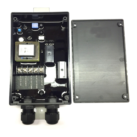
RF120V-2WP Instructions
This receiver is a 340 MHz AC motor control, intended to be used in conjunction with the KF340-2 Transmitter. The
receiver can be configured for either momentary or latching operation. The unit operates on 120 VAC and provides
two isolated dry contact closures. All of the electronic components are encapsulated so the receiver is capable of
being operated in harsh environments.
Momentary and Latching Operation Setup:
To place a control in momentary mode set ALL 4 dip switch settings to the OFF position
In momentary mode the relay output is energized as long as a transmitter button is held down. Once the button is
released operation will stop.
To place a control in latching mode set ALL 4 dip switch settings to the ON position
Pressing the transmitter button once will energize the relay output. Pressing the same button a second time will de-
energize the relay output.
Programming Instructions:
Each keyfob transmitter has its own unique internal address that is transmitted whenever a button on the keyfob is
pressed. The receiver needs to be programmed to respond only to keyfob transmitters it is intended to operate with.
The following steps configure the receiver to operate with a particular keyfob transmitter(s). Up to twelve keyfob
transmitters can be programmed to one receiver. Please read the entire programming procedure before starting.
Prior to programming the receiver, verify that the receiver is connected to the input power. When the receiver enters
program mode, all previous transmitter addresses that were programmed will be erased from the receiver's
memory.
1. Locate the PROGRAM pushbutton on the receiver. Press and hold this button until the red LED next to the
program button illuminates (approximately 5 seconds). The receiver is now in the transmitter program mode.
Release the button. At this point all previously programmed transmitter addresses are erased from the receiver's
memory.
2. Press any button on the keyfob transmitter and verify that the red LED on the receiver extinguishes and then
illuminates (blinks once). Release the button.
3. Repeat previous step for additional key fob transmitters that will operate with this particular receiver. The red LED
on the receiver will extinguish and illuminate one time for the first transmitter being programmed, twice for the
second, three times for the third, four times for the fourth etc. The receiver will not respond to transmitters that have
already been programmed.
NOTE: All transmitters must be programmed at the same time. Once the control exits
program mode, as described in step 4, additional transmitters cannot be added. Once the receiver is put back into
program mode all previously programmed transmitters will be erased.
4. After 5-seconds of no switch being pressed on the transmitter(s) the receiver will return to normal operation. The
red LED on the receiver will blink rapidly, then extinguish. The receiver is now in the normal mode of operation. This
completes the programming instructions. The receiver will retain all of it's programming even when power is
removed.
Long Range Functionality
The receiver is setup to accept the GAMA Electronics long range antenna (part number LRA-340). The antenna can
be used to extend the standard 100' range of the RF system to ~500'. If you are planning to use a long range
antenna you will need to clip the long range antenna jumper and plug your long range antenna into the long range
antenna jack. If you purchased the long range system the unit will be shipped with this modification.
WARNING:
ONCE THE JUMPER HAS BEEN CUT THE INTERNAL ANTENNA WILL NOT FUNCTION. A LONG RANGE
ANTENNA WILL BE REQUIRED FOR OPERATION ONCE REMOVED.
Advertisement

Related Manuals for GAMA Electronics RF120V-2WP

Summary of Contents for GAMA Electronics RF120V-2WP
- Page 1 Long Range Functionality The receiver is setup to accept the GAMA Electronics long range antenna (part number LRA-340). The antenna can be used to extend the standard 100’ range of the RF system to ~500’. If you are planning to use a long range antenna you will need to clip the long range antenna jumper and plug your long range antenna into the long range antenna jack.
- Page 2 All manuals and user guides at all-guides.com RF120V-2WP Wiring Diagram 120V AC Motor - AC OUT UP - AC OUT DOWN - AC OUT COMM 120V - AC IN NEUT Power - AC IN LINE Source 1. Dip Switch for Momentary/Latching Operation 5.