Advertisement
Quick Links
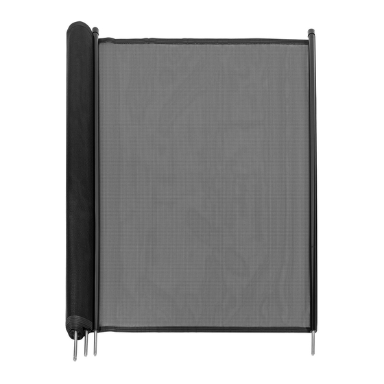
POOL SAFETY FENCE
ITEM # 90121 BLACK, 90130 BEIGE
OWNER'S MANUAL AND SAFETY INSTRUCTIONS
SAVE THIS MANUAL. KEEP THIS MANUAL FOR SAFETY WARNINGS, PRECAUTIONS, ASSEMBLY,
OPERATION, INSPECTION, MAINTENANCE AND CLEANING PROCEDURES. WRITE THE PRODUCT'S
SERIAL NUMBER ON THE BACK OF THE MANUAL, OR THE MONTH AND YEAR OF PURCHASE IF
PRODUCT HAS NO SERIAL NUMBER
FOR QUESTIONS, PLEASE CALL CUSTOMER SERVICE: 909.628.0880
Advertisement

Summary of Contents for XtremepowerUS 90121
- Page 1 POOL SAFETY FENCE ITEM # 90121 BLACK, 90130 BEIGE OWNER’S MANUAL AND SAFETY INSTRUCTIONS SAVE THIS MANUAL. KEEP THIS MANUAL FOR SAFETY WARNINGS, PRECAUTIONS, ASSEMBLY, OPERATION, INSPECTION, MAINTENANCE AND CLEANING PROCEDURES. WRITE THE PRODUCT’S SERIAL NUMBER ON THE BACK OF THE MANUAL, OR THE MONTH AND YEAR OF PURCHASE IF PRODUCT HAS NO SERIAL NUMBER FOR QUESTIONS, PLEASE CALL CUSTOMER SERVICE: 909.628.0880...
-
Page 2: Safety Warnings
SAFETY WARNINGS Read all safety warnings and instructions. Failure to follow the warnings and instructions may result in injury and/or property damage. Save all warnings and instructions for future reference. The warning and safety instructions in this manual are not meant to cover all possible conditions and situations that may occur. -
Page 3: Installation
INSTALLATION TO INSTALL THE POOL FENCE, YOU WILL NEED THE FOLLOWING TOOLS: Hammer Drill 5/8” Masonry Bit Extension Cord Tape Measure Hammer Marker Garden Hose Scissors Stapler Chalk 1/8” Drill Bit Screw Gun Square Head Screw NOTE: Before marking out the fence segments, make sure there is ample space between the fence and pool edge. - Page 4 ASSEMBLY INSTALLATION SPECIFICATIONS / TROUBLESHOOTING STEP 4: Next, place the stencil over the and mark the next hole. Repeat this step until you get to the 5th part of the segment. Mark the last hole for that segment. STEP 5: For the double hole on the stencil, adjust it to be over the 5th marked hole of the next segment to the right.
- Page 5 INSTALLATION MAKING THE CUSTOM CUT: This is for the segment of fence that will be shorter than the others. Usually this will be at the back for the pool. This last piece will most likely have fewer holes in it. Make sure when measuring the custom cut that the moldings face away from the pool.
- Page 6 ASSEMBLY INSTALLATION SPECIFICATIONS / TROUBLESHOOTING NOTE: To determine the lean of the angle, look at the hole in front of you. If you can connect all three holes with a triangle, the point of the triangle indicates the direction of the lean. The further away from the imagined line, the more lean of an angle you will need to drill.
- Page 7 INSTALLATION With your tape measure on the outside of the Cut the mesh with scissors. Use your measuring molding, make a mark on the top and bottom tape as a guide as you cut to make sure of the border using a marker. you are cutting the mesh at the correct measurement.
-
Page 8: Please Read The Following Carefully
DISCLAIMER PLEASE READ THE FOLLOWING CAREFULLY THE MANUFACTURER AND/OR DISTRIBUTOR HAS PROVIDED THE PARTS LIST AND ASSEMBLY DIAGRAM IN THIS MANUAL AS A REFERENCE TOOL ONLY. NEITHER THE MANUFACTURER OR DISTRIBUTOR MAKES ANY REPRESENTATION OR WARRANTY OF ANY KIND TO THE BUYER THAT HE OR SHE IS QUALIFIED TO MAKE ANY REPAIRS TO THE PRODUCT, OR THAT HE OR SHE IS QUALIFIED TO REPLACE ANY PARTS OF THE PRODUCT.