
Related Manuals for autosen AS002


Summary of Contents for autosen AS002
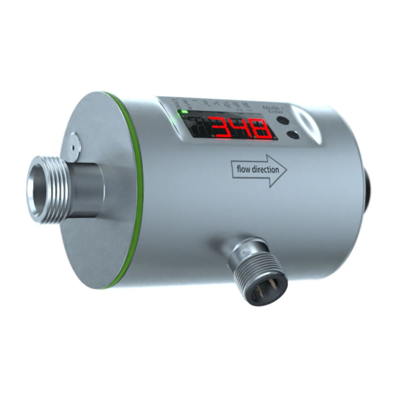
- Page 1 Operating instructions Magnetic-inductive flow meter AS002, AS003 autosen AS004...
-
Page 2: Table Of Contents
Contents 1 Preliminary note ���������������������������������������������������������������������������������������������������4 2 Safety instructions �����������������������������������������������������������������������������������������������4 3 Functions and features ����������������������������������������������������������������������������������������5 4 Function ���������������������������������������������������������������������������������������������������������������5 4�1 Processing of the measured signals ��������������������������������������������������������������6 4�2 Direction of flow ���������������������������������������������������������������������������������������������6 4�2�1 Determination of the direction of flow (Fdir) ������������������������������������������6 4�2�2 Detection of the direction of flow (dir�F) ������������������������������������������������7 4�3 Consumed quantity monitoring (ImP) ������������������������������������������������������������7 4�3�1 Display and counting method of the quantity meter �����������������������������8 4�3�2 Consumed quantity monitoring via pulse output �����������������������������������8... - Page 3 10�2 Settings for volumetric flow monitoring ������������������������������������������������������26 10�2�1 Limit monitoring volumetric flow (OUT1) ������������������������������������������26 10�2�2 Limit monitoring volumetric flow (OUT2) ������������������������������������������26 10�2�3 Analogue output flow rate (OUT2) ����������������������������������������������������26 10�2�4 Detection of the direction of flow (OUT1 or OUT2) ���������������������������26 10�3 Settings for consumed quantity monitoring �����������������������������������������������27 10�3�1 Quantity monitoring by pulse output (OUT1) ������������������������������������27 10�3�2 Quantity monitoring by preset counter (OUT1) ���������������������������������27 10�3�3 Pulse value ���������������������������������������������������������������������������������������27...
-
Page 4: Preliminary Note
1 Preliminary note ► Instructions > Reaction, result […] Designation of keys, buttons or indications → Cross-reference Important note Non-compliance may result in malfunction or interference� Information Supplementary note� 2 Safety instructions • Please read this document prior to set-up of the unit� Ensure that the product is suitable for your application without any restrictions�... -
Page 5: Functions And Features
► Protect the housing against contact with flammable substances and uninten- tional contact� To do so, equip the units with suitable protection (e�g� protective cover)� ► Do not press the pushbuttons manually� instead use another object (e�g� ballpoint pen)� 3 Functions and features The unit monitors liquid media�... -
Page 6: 4�1 Processing Of The Measured Signals
4.1 Processing of the measured signals The unit generates 2 output signals according to the parameter settings: OUT1/IO-Link: 4 selection options Parameter setting - Switching signal for volumetric flow quantity limit → 10.2.1 - Pulse signal for quantity meter → 10.3.1 - Switching signal for preset counter → 10.3.2 - Switching signal for direction of flow → 10.2.4... -
Page 7: 4�2�2 Detection Of The Direction Of Flow (Dir
4.2.2 Detection of the direction of flow (dir.F) When dir.F is activated (→ 10.2.4), the direction of flow is indicated by a switching signal� The output is switched on until the set minimum volumetric flow quantity in nega- tive direction of flow (- LFC) is not reached (1)� Afterwards the following applies: - The output switches ON when + LFC is exceeded (2)� - The output switches OFF when - LFC is not reached (3)�... -
Page 8: 4�3�1 Display And Counting Method Of The Quantity Meter
4.3.1 Display and counting method of the quantity meter Meter reading: • The current meter count can be indicated (→ 11.2). • In addition the value before the last reset is saved� This value can also be displayed (→ 11.2). The meter saves the totalled volumetric flow quantity every 10 minutes� After a power failure this value is available as the current meter reading�... -
Page 9: 4�3�3 Consumed Quantity Monitoring Via Preset Counter
FPro = 0 + FPro = – + + Q = volumetric flow quantity in positive direction - Q = volumetric flow quantity in negative direction V = volumetric flow quantity absolute (= sum of negative and positive flow) 4.3.3 Consumed quantity monitoring via preset counter 2 kinds of monitoring are possible which can be set via the parameter [rTo]�... -
Page 10: 4�4 Switching Function
4.4 Switching function OUTx changes its switching status if it is above or below the set switching limits (flow or temperature)� Hysteresis or window function can be selected� Example of volumetric flow monitoring: Hysteresis function Window function SP = set point SP = upper limit rP = reset point rP = lower limit... - Page 11 • If the measured value is outside the measuring range or in the event of an internal error, the current or voltage signals indicated in Figure 1, Table 2 are provided� • The measuring range is scalable: [ASP2] determines at which measured value the output signal is 4 mA or 0 V� [AEP2] determines at which measured value the output signal is 22 mA or 10 V�...
- Page 12 [mA] FOU=On 11,5 21,5 FOU=OFF cr.UL UL cr.OL -130 -120 [% MEW] [°C] [°F] Figure 1: Characteristics of the analogue output according to the standard IEC 60947-5-7� Flow (a negative flow value means flow against the marked flow direction) Temperature Below the display range Above the display range cr�UL:...
-
Page 13: 4�6 Measured Value Damping (Dap)
4.6 Measured value damping (dAP) The damping time allows to set after how many seconds the output signal has reached 63 % of the final value if the flow value changes suddenly� The set damp- ing time stabilises the outputs, the display and the process value transfer via the IO-Link interface. The signals [UL] and [OL] (→ 12 Troubleshooting) are defined under consideration of the damping time�... - Page 14 Example: dSt for hysteresis function Condition Reaction 1 Volumetric flow quantity Q reaches LFC dST starts, output becomes active 2 dST elapsed, Q reached SP Output remains active 3 Q below SP but above rP Output remains active 4 Q below rP Output is reset 5 Q reaches again LFC dST starts, output becomes active...
-
Page 15: 4�8 Low Flow Cut-Off (Lfc)
Example: dSt for window function Condition Reaction 1 Volumetric flow quantity Q reaches LFC dST starts, output becomes active 2 dST elapsed, Q reached good range Output remains active 3 Q above SP (leaves good range) Output is reset 4 Q again below SP Output becomes active again 5 Q below rP (leaves good range) Output is reset again... -
Page 16: Mounting
For the IODDs necessary for the configuration of the unit, detailed information about process data structure, diagnostic information and parameter addresses visit www�autosen�com� 5 Mounting ► Ensure that the system is free of pressure during installation� ► Ensure that no media can leak at the mounting location during installa- tion�... -
Page 17: 5�2 Not Recommended Installation Position
5.3 Installation in pipes The units with a G thread can be installed in the pipes using adapters� Information about the available mounting accessories at www�autosen�com� 1� Grease the threads of the process connection, adapter and sensor� Use a lubricating paste which is suitable and approved for the application�... -
Page 18: 5�4 Grounding
2� Screw the adapter (B) into the pipe (A)� 3� Place the seals (C) and install the unit according to the marked flow direction� 4� Screw the adapter (B) with the threads (D) until it is hand-tight� 5� Tighten the two adapters in opposite direction (tightening torque: 30 Nm)� After installation air bubbles in the system can affect the measurement�... - Page 19 Sample circuits: 2 x positive switching 2 x negative switching 1 BN 1 BN 2 WH 2 WH 4 BK 4 BK 3 BU 3 BU 1 x positive switching / 1 x analogue 1 x negative switching / 1 x analogue 1 BN 1 BN 2 WH...
-
Page 20: Operating And Display Elements
7 Operating and display elements Mode / Enter 1-6: Indikator-LEDs für Prozesswertanzeige Process value display Unit Current flow volume per minute l/min Current flow volume per hour Current consumed quantity (= meter reading) since the last reset 4 + 6 x 10 Consumed quantity (= meter reading) before the last reset... - Page 21 7-8: Indicator LEDs for switching output LED 7: Switching status OUT2 (lights when output 2 is switched) LED 8: Switching status OUT1 (lights when output 1 is switched) 9: Alphanumeric display, 4 digits • Current volumetric flow quantity with setting [SELd] = FLOW • Meter reading of the totaliser with setting [SELd] = TOTL • Current medium temperature with setting [SELd] = TEMP • Parameters and parameter values...
-
Page 22: Menu
8 Menu Hi.F l/min °C Lo.F Hi.T Lo.T FOU1 FOU2 ImPS ImPR Hno Hnc Fno Fnc ImP dir.F I U Hno Hnc Fno Fnc In.D dir.F ASP2 DIn2 SELd SEL2 AEP2 FPro Fdir [Mode / Enter] [Set] Parameters with white background are indicated in case of factory setting (→ 14). Parame- ters with grey background are indicated in case of changes of the preset for ou1 and ou2�... - Page 23 Parameters Explanation and setting options (→ 4 Function) SP1 / rP1 Maximum / minimum value for volumetric flow on OUT1� ImPS Pulse value = volumetric flow quantity at which 1 pulse is delivered� ImPR Configuration of the output for consumed quantity monitoring: YES (pulse signal), no (switching signal)�...
-
Page 24: Set
LFC Low flow cut-off� FPro Counting method of the totaliser: – + or 0+ (→ 10.5.8). Fdir Direction of flow: + or - (→ 10.5.9). rES Restoring the factory settings� 9 Set-up After power on and expiry of the power-on delay time of approx� 5 s the unit is in the RUN mode (= normal operating mode)� It carries out its measurement and evaluation functions and generates output signals according to the set parame- ters�... -
Page 25: 10�1 Parameter Setting In General
CAUTION For medium temperatures above 50 °C (122 °F) some parts of the housing can heat up to over 65 °C (149 °F)� ► Do not press the pushbuttons manually� Instead use another object (e�g� ballpoint pen)� 10.1 Parameter setting in general 1�... -
Page 26: 10�1�2 Locking / Unlocking
10.1.2 Locking / Unlocking The unit can be locked electronically to prevent unintentional settings� On delivery: not locked� Locking ► Make sure that the unit is in the normal operating mode� ► Press [Mode/Enter] and [Set] simultaneously for 10 s until [Loc] is displayed�... -
Page 27: 10�3 Settings For Consumed Quantity Monitoring
10.3 Settings for consumed quantity monitoring 10.3.1 Quantity monitoring by pulse output (OUT1) ► Select [ou1] and set ImP� ► Select [ImPR] and set YES� ► Select [ImPS] and set the volumetric flow quantity at which 1 pulse is provided (→ 10�3�3)� 10.3.2 Quantity monitoring by preset counter (OUT1) ► Select [ou1] and set ImP� ►... -
Page 28: 10�3�5 Time-Controlled Counter Reset
10.3.5 Time-controlled counter reset ► Select [rTo] and set the requested value (intervals of hours, days or weeks)� > The counter is reset automatically with the value now set� 10.3.6 Deactivation of the counter reset ► Select [rTo] and set OFF� >... -
Page 29: 10�5�2 Standard Display
10.5.2 Standard display ► Select [SELd] and define the standard unit of measurement FLOW = display shows the current volumetric flow value in the standard unit of meas- urement� TOTL = display shows the current meter reading in the unit providing the highest accuracy�... -
Page 30: 10�5�7 Low Flow Cut-Off
10.5.7 Low flow cut-off ► Select [LFC] and set the limit� 10.5.8 Counting method of the totaliser ► Select [FPro] and set the value: -+ = totalling the volumetric flow values with the correct sign� 0+ = totalling only positive volumetric flow values� 10.5.9 Direction of flow ►... -
Page 31: Operation
11 Operation 11.1 Reading the process value The LEDs 1-6 signal which process value is currently displayed� The process value to be displayed as standard (temperature, volumetric flow quantity or meter reading of the totaliser) can be preset → 10.5.2 Standard display� A standard unit of measurement can be defined for the volumetric flow quantity → 10�5�1� 11.2 Changing the process value display in the RUN mode ►... - Page 32 Display Type Description Fault correction C�Loc Warning Setting buttons on the unit ► Finish parameter setting via temporarily locked, parameter IO-Link communication� setting via IO-Link communica- tion active� S�Loc Warning Setting buttons locked via ► Unlock the unit via IO-Link parameter software, parameter interface using the parame- change rejected�...
-
Page 33: Technical Data
13 Technical data Technical data and scale drawing at www�autosen�com�... -
Page 34: Factory Setting
14 Factory setting Factory setting User setting 20 % 19�5 % ImPS 0�01 l ImPR SP2 (FLOW) 40 % rP2 (FLOW) 39�5 % SP2 (TEMP) 40 % rP2 (TEMP) 39�5 % ASP2 (FLOW) AEP2 (FLOW) 100 % ASP2 (TEMP) ASP2 (TEMP) 100 % Fdir FPro... - Page 35 SELd FLOW SEL2 FLOW The percentage values refer to the final value of the measuring range� Technical data, approvals, accessories and further information at www�autosen�com�...
Need help?
Do you have a question about the AS002 and is the answer not in the manual?
Questions and answers