Table of Contents
Advertisement
Quick Links
Advertisement
Table of Contents

Related Manuals for e-survey ESL2

Summary of Contents for e-survey ESL2
- Page 1 INSTRUCTION MANUAL Automatic Level ESL2...
-
Page 2: Table Of Contents
Contents 1. Equipment....................5 2. Applications ....................5 3. Technical Data....................6 4. Description....................7 4.1 Instrument..................8 4.2 Leveling Staffs..................9 4.3 Tripod....................10 5. Instructions for Use ................... 10 5.1 Unpacking and Setting Up..............10 5.2 Leveling Up..................10 5.3 Focusing and Sighting .............. - Page 3 6.2 Distance Measurement from Stadia Readings (fig.2) ...... 15 6.3 Precise Height Measurement with ESM1 (fig.3)........16 7. Testing and Adjusting................. 19 7.1 Tripod....................19 7.2 Circular Level(fig.5) ................19 7.3 Horizontality of the Line of Sight ............ 21 8. Care and Transport ..................24 8.1 Transport ..................
-
Page 4: Equipment
0.01mm 2. Applications Model ESL2 Automatic Level is adoptable for the second and third class leveling, It is also used for general construction engineering and installation of large size machines. The advantage of the automatic is that as soon as the circular bubble is centered, the line of sight is horizontal for all pointings of the telescope. -
Page 5: Technical Data
3. Technical Data ESL2 ESL2+ESM1 Standard deviation of 1KM ±1.0mm ±0.5mm double run Telescope Image Erect Magnification Clear objective aperture 45mm Shortest focusing distance 1.6m Multiplication factor Additive constant Compensator Working range ±14′ Setting accuracy ≤0.3″ Circular level sensitivity 8′/ 2mm Horizontal circle 360°(400g) -
Page 6: Description
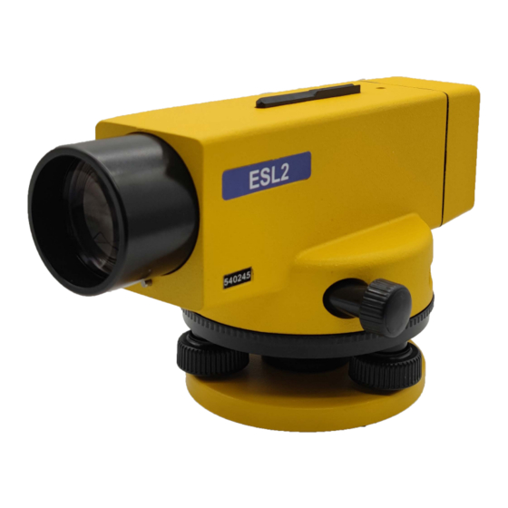
4. Description ESL2 Fig.1 Automatic Level 1. Base plate 6. Telescope eyepiece 2. Footscrew 7. Press button 3. Horizontal drive, endless 8. Circular level 4. Telescope objective housing 9. Prism for viewing circular level 5.Optical sight 10. Focussing knob with cores/fine motion... -
Page 7: Instrument
4.1 Instrument The base plate (1) has a standard thread enabling the ESL2 to be used on any of our tripods which are sufficiently stable (and on any other tripod having a 5/8″thread fixing screw). The rotatable upper part of the instrument consists chiefly of the telescope with an optical mechanical compensator. -
Page 8: Leveling Staffs
4.2 Leveling Staffs As the telescope of the ESL2 gives an erect image, leveling staffs with erect numbers should be used. It is emphasized that the accuracy of leveling... -
Page 9: Tripod
High quality staffs must be used. 4.3 Tripod For normal leveling the model L tripod with telescopic legs is usually preferred. For precise leveling and severe conditions e.g. strong wind the model M tripod is recommended. As the fixing screw on all of our tripods have the same thread however, any our tripods can be used. -
Page 10: Focusing And Sighting
set by the compensator to horizontal. For adjustment of the circular level, please refer 7.2. 5.3 Focusing and Sighting The telescope is pointed towards a uniformly light surface. Or a sheet of white paper and the telescope eyepiece (6) is turned until he reticle cross-hairs appear sharp and absolutely black. -
Page 11: Measuring
The press button also verifies the leveling up of the ESL2, because the staff image will not show the correct movement on pressing the button if the circular level is a long away from its central position, but the movement will be quicker and shorter due to the pendulum reaching its stop line. -
Page 12: Normal Height Measurement
temperature. 6.1 Normal Height Measurement Procedure: 1. After pointing at the staff, check the circular bubble is centered, then press the push button to verify that the compensator is functioning and finally read the position of the horizontal cross hair on the staff. 2. - Page 13 Example: Horizontal cross hair 1.143m Upper stadia A1 1.216m Lower stadia A2 1.068m 1/2(A1+A2) 1.142m Should the telescope image tremble due to ground vibrations or a strong wind, the observer can reduce the effects by holding the tripod legs at about their mid-point. Fig.2...
-
Page 14: Distance Measurement From Stadia Readings (Fig.2)
To obtain the distance, the readings of the upper (A1) and lower (A2) stadia hairs are used. The difference between the two readings multiplied by 100 gives the horizontal distance from instrument to the staff (see fig.3) ESL2 field of view with leveling staff Height reading from horizontal hair 1.143m Example: Upper stadia A1 1.216m... -
Page 15: Precise Height Measurement With Esm1 (Fig.3)
6.3 Precise Height Measurement with ESM1 (fig.3) For leveling work of very high accuracy the ESL2 is used with the parallel ESM1. plate micrometer micrometer slipped onto telescope objective and locked in position by turning the locking knob. Reading magnifier... - Page 16 In sloping terrain, the lower part of the staff should not be used, as refraction close to the ground can cause errors. In sunny weather an umbrella should be used to shelter the instrument to ensure that the level is protected from the glare of the sun. Procedure: 1.
- Page 17 serves as a check. Example above: Staff reading 77cm Micrometer reading 0.556cm Height 77.556cm Fig.4...
-
Page 18: Testing And Adjusting
7. Testing and Adjusting 7.1 Tripod There should be no play between the various components of the tripod. The hexagonal key should be used to tight up the tripod screws when necessary. The hinges between the tripod head and the legs can be adjusted; they should be sufficiently stiff so that when the tripod is lifted by its head, the legs just remain spread-out. - Page 19 Fig.5 Adjusting the circular bubble. As an adjustment screw is tightened the bubble runs towards it and, as it is loosened, the bubble runs away from it. The first adjustment screw to be turned, therefore, is the one that is the nearest to being in line with the middle of the bubble and the centre of the setting circle.
-
Page 20: Horizontality Of The Line Of Sight
7.3 Horizontality of the Line of Sight 7.3.1 Testing (Fig.6) In flat terrain a test bay, between 45m and 60m long, is selected and divided into three equal sections of length d, A staff is set up on an iron ground plate or peg at each of the intermediate points B and C (if only one staff is used it must be moved as required from point B to point C). - Page 21 a4’ – a1’ = a3’ – a2’ than a4’ = a1’ – a2’ + a3’ If the actual reading a4’ differs from the computed correct value a4 by more than 2mm in 30m, the whole procedure must be repeated. If the difference is confirmed, the line of sight must adjusted as described Fig.6 Fig.6 Testing the horizontality of the line of sight...
- Page 22 In 7.3.2 the tolerance of 2mm in 30m is a practical value for routine leveling with the instrument. If necessary, however, a customer can make a more precise adjustment. 7.3.2 Adjusting (Fig.6 and Fig.7) Fig.7 Fig.7 Adjusting the line of sight The instrument is still at D.
-
Page 23: Care And Transport
from the instrument container, carefully turn the adjusting screw until the horizontal hair gives the computed correct reading a4 on staff B. The last turn of the adjustment screw should be clockwise, i.e. to the left. Screws on the protective cover and finally repeat the test (7.3.1) to verify the adjustment. 8. -
Page 24: Storage
Shipping When transporting the product by rail, air or sea, always use the complete original packaging, transport container and cardboard box, or its equivalent, to protect against shock and vibration. Field adjustment After transport inspect the field adjustment parameters given in this user manual before using the product. -
Page 25: Cleaning And Drying
in this user manual before using the product. 8.3 Cleaning and Drying Product and Accessories • Blow dust off lenses. • Never touch the glass with your fingers. • Use only a clean, soft, lint-free cloth for cleaning. If necessary, moisten the cloth with water or pure alcohol. Do not use other liquids;... - Page 26 NOTE: These designs, figures and specifications are subject to change without notice. We shall not be held liable for damages resulting from errors in this instruction manual.
Need help?
Do you have a question about the ESL2 and is the answer not in the manual?
Questions and answers