
Related Manuals for Sabre ED-35

Summary of Contents for Sabre ED-35
- Page 1 PUBLIC ADDRESS MIXER AMPLIFIER AMPLIFIER MODEL: ED-35 ED-65 Warning:Before attempting to connect,operate or adjust this Amplier, please read these instructions completely and carefully and save this Manual...
-
Page 3: Table Of Contents
Table of Contents Table of Contents Introductions ----------------------------------------- 2 Features -----------------------------------------------3 Controls------------------------------------------------ 4 Setups --------------------------------------------------5 Wiring Guide ------------------------------------------5 Connections ------------------------------------------7 Operations-------------------------------------------- 9 MOH---------------------------------------------------10 Block Diagram --------------------------------------11 Specifications --------------------------------------12... -
Page 4: Introductions
Introductions Welcome Congratulation and thank you for the purchasing ED-35 or ED-65, a multi-function commercial amplier.These ampliers are designed to provide a big impact in sound reproduction and to produce the best and highest quality audio at an affordable price. We wish you great enjoyment and satisfaction when using your amplier, whether you are an installation, or... -
Page 5: Features
Features Features The ED-35 or ED-65 mixer ampliers are comprehensive, all-in-one mixer-amplier solutions for commercial and industrial applications. These low-cost units provide all necessary features in a simple building-block format. * Three microphone and two line inputs with XLR,1/4” TRS jacks and RCA jacks. -
Page 6: Controls
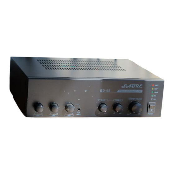
Controls Controls FRONT PANEL [ Figure 1.1 Front panel diagram ] 1.Input channel volumes. 2.Two bands tone controls ( 100Hz/10KHz ). 3.Master volume control. 4.Indicators ( Protection/Output level/Power ). 5.Power switch. 6.AUX INPUT Rear Panel [ Figure 1.2 Rear panel diagram ] 1.Power cable. -
Page 7: Setups
Setups Setups Installation CAUTION : Before you begin, make sure your mixer-amplier is disconnected from the power source, with the power switch in the “OFF” position and all level controls turned completely down (counterclockwise). You may stack mixer-ampliers without using a cabinet or you may place a single mixer-amplier on a surface with 12-inches (about 30cm) of air space around the unit for convection cooling. - Page 8 Setups Choose output wire and connectors For the amplier output connectors, We recommends using pre-built or professionally wired, high-quality, and heavy gauge speaker wires. You may use EURO blocks for your output con- nectors. To prevent the possibility of short-circuits, wrap or otherwise insulate exposed loud- speaker cable connectors.
-
Page 9: Connections
100V, COM for constant-voltage speaker loads. Oconnect the COM terminal to speaker negative(-) lead; connect one of the other terminals to speaker positive(+) lead. The impedance and output voltage are same as following Table 2.1 ED-35 140Ω / 70V 285Ω / 100V 75Ω / 70V 154Ω... - Page 10 Connections CAUTION : Never use both the Low-Z(4Ω / 8Ω)and Hi-Z(70V, 100V) terminals at the same time 100V [ Figure 2.3 Wrong connection ]...
-
Page 11: Operations
Operations Operations Telephone paging Connect mixer-amplier TELE-PAGING connector to telephone interface unit/PBX like telephone pager. You can announce by telephone after dial up to telephone interface unit/PBX. [ Telephone pager/PBX ] [ Figure 3.1 Telephone paging connecon ] Signal input gain control Mixer-amplier can accept variable and wide range input signal with trim pot. -
Page 12: Moh
For 2-Channel Broadcast below Example can be Performed When the Unit is used in conjunc-tion with the Optional ED-35 or ED-65. -
Page 13: Block Diagram
Block diagram Block diagram... -
Page 14: Specifications
Specifications Specifications Performance ED-35 ED-65 Input Sensitivity for full output at maximum gain Balanced Microphone Channels -50dB ± 3dB Unbalanced AUX Channels -30dB ± 3dB Tele-Paging -21dB ± 3dB Frequency Response at 1watt from speaker out tap, 80Hz ~18kHz +1.5/-3dB...
Need help?
Do you have a question about the ED-35 and is the answer not in the manual?
Questions and answers