Table of Contents
Advertisement
Quick Links
Advertisement
Table of Contents

Related Manuals for GF Piping Systems NeoFlow

Summary of Contents for GF Piping Systems NeoFlow
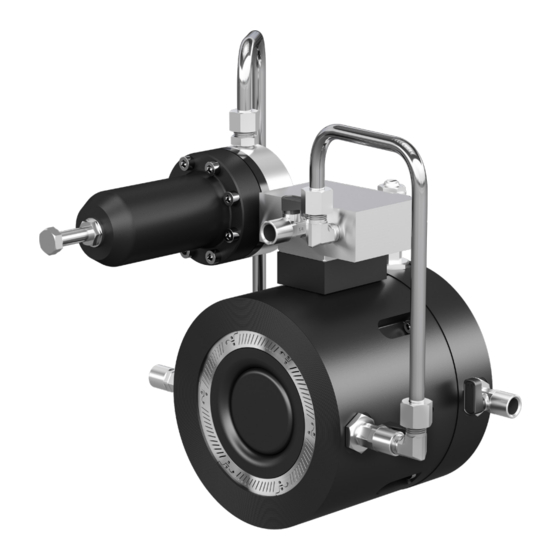
- Page 1 GF Piping Systems Operating instructions NeoFlow Pressure Reducing Valve DN50 - DN150 The NeoFlow Pressure Reducing Valve is co-developed with OFUI 1276507 GFDO_MA_00049 / 1a (05.2021) © Georg Fischer Piping Systems Ltd 8201 Schaffhausen/Schweiz...
- Page 2 GF Piping Systems English Deutsch French Spanish Italian Portuguese Nederlands Chinese The nNeoFlow Pressure Reducing Valve is co-Developed with OFUI...
- Page 3 GF Piping Systems Instruction manual NeoFlow pressure reducing valve DN50 - DN150...
- Page 4 GF Piping Systems Translation of the original instruction manual Disclaimer The technical data within this document is not binding. It does not constitute expressly warranted characteristics, guaranteed properties or guaranteed durability. It is subject to modification. Our General Terms of Sale apply.
-
Page 5: Table Of Contents
Instruction manual NeoFlow pressure reducing valve Table of contents Product description Intended use EC Manufacturer's declaration Technical data Safety Information Observe instruction manual! Commissioning and use by qualified personnel only Storage and transport Warning signals Other applicable documents Pressure test of piping systems... - Page 6 NeoFlow pressure reducing valve Instruction manual Cleaning filter and control system Removal of the NeoFlow pressure reducing valve De-installation of the control system Maintenance of the control system Troubleshooting Reducing outlet pressure fluctuations Flow chart A Flow chart B Disposal Spare parts list 10.1...
-
Page 7: Product Description
Foreseeable misuse The NeoFlow pressure reducing valve may not be used as a pure shut-off valve. Media other than water as well as water containing an amount of disinfectant may only be used in consultation with a contact partner from GF Piping Systems. The use of solid matter in the medium can affect the function of the NeoFlow pressure reducing valve. -
Page 8: Technical Data
NeoFlow pressure reducing valve Instruction manual Technical data 1.3.1 Specifications Specifications Pressure ratings and perfor- Maximum inlet pressure P1 16 bar* mance Maximum outlet pressure P2 16 bar** Outlet pressure range 0.1 to 16 bar** Minimal pressure difference P1– P2 0.2 bar***... -
Page 9: Safety Information
Instruction manual NeoFlow pressure reducing valve Safety Information Observe instruction manual! The instruction manual is part of the product and an important component within the safety concept. Non-observance may lead to severe injuries. Read and observe instruction manual. • Always have instruction manual available by the product. -
Page 10: Other Applicable Documents
Quick start instructions NeoFlow pressure reducing valve DN50-DN150 700278143 These documents are available through agents of GF Piping Systems or at www.gfps.com. Pressure test of piping systems The system test pressure (STP) must be determined for all pipes based on the system operating pressure (MDP). If the water surge... -
Page 11: Design And Function
Instruction manual NeoFlow pressure reducing valve Design and function Subassemblies Designation Main Body Control block Pilot valve Inlet control line Outlet control line Direction of flow medium Designations of the valves Ball valve Designation Ball valve inlet Ball valve outlet... -
Page 12: Mode Of Operation
Adjustable outlet pressure The axial movement of the valve piston (4) in the main body (1) results in flow changes in the NeoFlow pressure reducing valve and thus regulates the existing outlet pressure (P2). The position of the valve piston (4) is regulated by the prevalent pressure of the control area (5). -
Page 13: Installation Process
Default outlet pressure! The outlet pressure is default on delivery ► The default outlet pressure of the NeoFlow pressure reducing valve with black color coding of the pilot valve spring is 3 bar. CAUTION! Use of an incompatible NeoFlow pressure reducing valve type! The manufacturer's specifications regarding the maximum pressure difference between the inlet pressure and the outlet pressure must be complied with. - Page 14 NeoFlow pressure reducing valve Instruction manual Open ball valves KH1, KH2 and KH3 and make sure that KH4, KH5, and KH6 are closed. Position 1: Ball valve KH closed Position 2: Ball valve KH open To allow monitoring of inlet pressure P1 and outlet pressure P2, it is recommended to connect a manometer to the ball valves KH6 (inlet pressure P1) and KH5 (outlet pressure P2).
- Page 15 Fully close the damping valve (DV) with a slotted screwdriver clockwise until a resistance is felt. The damping valve (DV) can be used to set the reaction time with which the stability of the control loop within the NeoFlow pressure reducing valve can be changed.
-
Page 16: Installation Area
Selection of the installation area ► Leave enough room for the installation, setting, and removal of the NeoFlow pressure reducing valve. ► If needed, additional measures must be made for the pilot regulator to protect it against frost, adverse effects of the weather, and floods. - Page 17 Configuration of the fittings with bypass lines For existing installations with bypass lines, the following configuration is recommended. ► The shut-off valves must be securely connected to the bypass line before the NeoFlow pressure reducing valve is put into ope- ration.
-
Page 18: Installation
► To prevent contamination, make sure that disinfection procedures are used on all connections. ► Ensure that the NeoFlow pressure reducing valve is suited for the operating conditions, see type plate. The use with unsuitable operating conditions can result in damage. - Page 19 ► We recommend use of a PP steel flange with a suitable profile seal. ► On one side of the NeoFlow pressure reducing valve, a space of at least 1.5 times the valve length must be maintained for access to the flange bolts. Ensuring that the bolts for the flange connection can be installed at least on one installation side.
-
Page 20: Initial Operation
Risk of injury due to uncontrollable exit of the medium! If the NeoFlow pressure reducing valve (N) is leaking or the ball valves KH 4-6 on the NeoFlow pressure reducing valve (N) are not closed, the medium may exit uncontrollably under high pressure. - Page 21 Instruction manual NeoFlow pressure reducing valve Open the hydrant (H) slowly. Allow a suitable flow rate to pass through the NeoFlow pressure reducing valve (N). Depending on the dimension: for example, DN100 5 l/s up to 10 l/s. With an outlet manometer KH5 check the outlet pressure P2 for stability after 10 minutes. The outlet pressure P2 is reached...
-
Page 22: Operation
NeoFlow pressure reducing valve Instruction manual Operation Setting outlet pressure P2 Slowly increase or decrease the spring tension of the pilot spring (AS) by turning the Adjusting screw pilot valve to achieve the desired outlet pressure P2. The following table provides information for this purpose. Ensure a change in the outlet pressure P2 takes place via an outlet manometer at KH5. - Page 23 Instruction manual NeoFlow pressure reducing valve Slightly open the outlet shut-off valve (O) slowly. Fully close the hydrant (H) slowly. Fully open the outlet shut-off valve (O). Using the Adjusting screw pilot valve (AS) to finalise the setting of the desired outlet pressure P2 (shown on the outlet mano- meter at KH5) and fix it with a locking nut.
-
Page 24: Service
Uncontrolled exit of the medium and/or flowing out of the medium from the open pipe and/or the valve. ► Do not use the NeoFlow pressure reducing valve as an end fitting. ► Completely relieve pressure from the pipe before dismantling. -
Page 25: Cleaning Filter And Control System
Cleaning filter and control system ATTENTION! The filter and control system of the NeoFlow pressure reducing valve can be serviced and cleaned under pressure. ► For this purpose, the ball valves KH1-6 must be in the stated position. Close the ball valves KH1-3 in in the following order: KH3, KH1, KH2 Carefully unscrew the filter sealing plug (5) and remove the filter (3). - Page 26 NeoFlow pressure reducing valve Instruction manual Flush the control system with water by slowly opening KH1 and KH2 very slowly and carefully after each other. CAUTION! Exiting medium! If the sealing plug is removed, the medium exits uncontrollably from the control block peeling body (1).
- Page 27 Instruction manual NeoFlow pressure reducing valve 10. To clean the pilot valve, unscrew the sealing plug (22), remove the control spring (21) and control cylinder (20) with the actuator pin (19) and blow out using compressed air. 11. Clean the sealing plug (22) and reassemble, glue the sealing plug (22) with bolt retention. Notice: After opening, the threads must be thoroughly cleaned and coated with sealing drinking water-safe thread glue during assembly, e.g.
-
Page 28: Removal Of The Neoflow Pressure Reducing Valve
Instruction manual Removal of the NeoFlow pressure reducing valve Shut off the NeoFlow pressure reducing valve with the two shut-off valves on the inlet and outlet (A and O). Make sure that all KH1-3 and KH5 - KH6 are open. - Page 29 Instruction manual NeoFlow pressure reducing valve Remove the NeoFlow pressure reducing valve. Use tools suitable for the removal and make sure that there is no mechanical strain on the piping system. ATTENTION! Exiting medium! The remaining medium between the shut-off valves A and O in the piping system may exit uncontrollably from the piping system when removing the NeoFlow pressure reducing valve.
-
Page 30: Installation Of The Control System
NeoFlow pressure reducing valve Instruction manual De-installation of the control system Bring the ball valves KH1-3 into the closed position. Completely loosen the nuts of the control lines (1-4) to remove the control lines on the inlet and outlets. Release the damping valve (DV) by loosening the retaining ring. - Page 31 Instruction manual NeoFlow pressure reducing valve Remove both bolts from the control block and lift the control system off the main body. Notice: The bolts are located underneath the “+GF+” sticker. The film can be penetrated by a pointy object, e.g. a screwdriver.
-
Page 32: Maintenance Of The Control System
NeoFlow pressure reducing valve Instruction manual Maintenance of the control system 7.5.1 Pilot valve Code Designation 173021000 Pilot valve repair kit 19 20 14 15 10 11 Designation Adjusting screw pilot valve (AS) Locking nut Indication disc Spring case Screws (8) for the spring case... - Page 33 Injury or material damage due to exiting medium. The following requirements must be met for carrying out the next steps: ► The NeoFlow pressure reducing valve must be removed from the piping system, see section «7.3 Removal of the NeoFlow pres- sure reducing valve»...
- Page 34 NeoFlow pressure reducing valve Instruction manual Remove the diaphragm casing (14) from the pilot body (17) and check the o-ring (16) for wear or damage. Replace if required. Cleaning To clean the pilot valve, unscrew the sealing plug (22), remove the control spring (21) and control cylinder (20) with the actuator pin (19), check all components for wear and and blow out using compressed air.
- Page 35 Tighten the 8 bolts for the spring case (4) crosswise to the torque value recommended on the nameplate using a torque wrench. 7.5.2 Control block ATTENTION! Damage during disassembly or assembly can impair the functionality of the NeoFlow pressure reducing valve. ► Handle components with care. Designation Control block peeler body...
- Page 36 Piston seal Guide pin Peeler body ► Remove the NeoFlow pressure reducing valve according to section «7.3 Removal of the NeoFlow pressure reducing valve» on page 26. Dismantling Loosen the casing bolts (2) all around to gain access to the internal o-rings.
- Page 37 Instruction manual NeoFlow pressure reducing valve Remove the valve piston (3). Check the o-ring (6) for wear or damage and replace, if required. Assembly Assembly is the reverse process. On reassembly, lightly lubricate all seals with a drinking-water safe lubricant such as Molyko- te 111 or Klübersynth UH1 64-2403.
-
Page 38: Troubleshooting
Reducing outlet pressure fluctuations The damping valve (DV) can be used to set the reaction time, thus changing the stability of the control loop within the NeoFlow pres- sure reducing valve can be changed. Reduction of the reaction time can improve the stability of the control loop. This makes the pressure cycle in the NeoFlow pressure reducing valve less susceptible to pressure fluctuations. - Page 39 Instruction manual NeoFlow pressure reducing valve If stability cannot be reached, repeat the procedure for adjusting the damping valve (DV) «5.1 Carrying out the basic setup» on page 11. ATTENTION! Pressure fluctuation despite adjustment of the damping valve! If, despite adjustment of the damping valve (DV) there are pressure fluctuations at the outlet manometer KH5, proceed as follows.
-
Page 40: Flow Chart A
NeoFlow pressure reducing valve Instruction manual Flow chart A The NeoFlow pressure reducing valve is exhibiting a faulty function (e.g. leakage, desired outlet pressure cannot be reached, or outlet pressure cannot be maintained). Are there any visible leaks on the... -
Page 41: Flow Chart B
NeoFlow pressure reducing valve (close stop at the shut-off valve on inlet side). Release outlet? pressure at KH4-6 - Uninstall NeoFlow pressure reducing valve and check for damage Address your GF Piping Systems contact partner if occurring errors cannot be fixed. -
Page 42: Disposal
Correct disposal! ► Separate materials (plastics, metals, etc.) and dispose of them in accordance with local regulations. If you have any questions regarding the disposal of the product, please contact your national GF Piping Systems representative. Spare parts list 10.1... -
Page 43: Accessories
Instruction manual NeoFlow pressure reducing valve Accessories 11.1 Manometer connections (optional) Measuring devices such as manometers can be installed on the ball valves KH4-6. Sensors can be connected directly to the ball valves via the standard ¼ inch internal thread. -
Page 44: Components And Subassemblies
NeoFlow pressure reducing valve Instruction manual Components and subassemblies 12.1 General overview Designation Pilot valve Hex plug Spacer plate Socket head bolt M6x25 Control block base Inlet ball valve Sealing plug 90° bolt connection Ball valve outlet Main body Ball valve control chamber... -
Page 45: Control Block
Instruction manual NeoFlow pressure reducing valve 12.3 Control block Designation Control block peeler body Label Filter O-ring sealing plug Filter sealing plug 12.4 Pilot valve 19 20 14 15 10 11 Designation Adjusting screw pilot valve (AS) Locking nut Indication disc... - Page 46 NeoFlow pressure reducing valve Instruction manual...
- Page 47 GF Piping Systems Worldwide at home Our sales companies and representatives ensure local customer support in more than 100 countries. www.gfps.com Argentina / Southern South America France Mexico / Northern Latin America Singapore Georg Fischer Central Plastics Sudamérica S.R.L. Georg Fischer SAS Georg Fischer S.A.
Need help?
Do you have a question about the NeoFlow and is the answer not in the manual?
Questions and answers