
Related Manuals for Kaidan Kiwi-L


Summary of Contents for Kaidan Kiwi-L
- Page 1 All manuals and user guides at all-guides.com KiWi™-L / Kiwi™+ User’ s Guide Photographic VR Panoramic Tripod Head Designed for the professional, priced for the novice...
- Page 2 Information in this manual is subject to change without notice and does not above), at Kaidan’s discretion. represent a commitment on the part of Kaidan. No part of this manual may be reproduced or transmitted in any form or by any means, electronic or mechani-...
-
Page 3: Unpacking The Box
Assembling the KiWi™ UNPACKING THE BOX The KiWi-L or the Kiwi + are shipped in a single box and con- sists of two major components. The components are detailed below. NOTE: Only the Kiwi+ is shipped with four detent discs (12,14,18, and 20 positions). - Page 4 All manuals and user guides at all-guides.com Assembling the KiWi ™ ATTACHING THE VERTICAL BRACKET To assemble the KiWi, simply slide the Vertical Bracket onto the Horizontal Bracket in the orientation shown in the various im- ages in this manual. Note: The bottom of the Vertical Bracket has a clamping mechanism with a spring-loaded nylon ball which keeps tension on the horizontal bracket while sliding the vertical bracket back and forth.
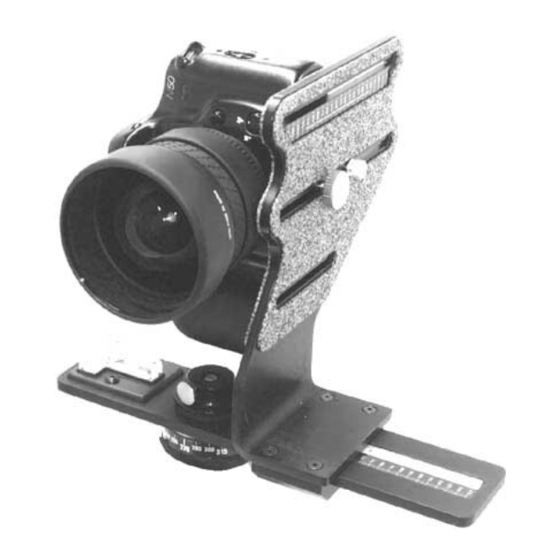
- Page 5 All manuals and user guides at all-guides.com Using the KiWi™ ATTACHING YOUR CAMERA To mount your camera, first select the appropriate slot in the Vertical Bracket that will best locate the tripod mounting thread on your camera. You may need to reposition the Captive Camera Knob in order to achieve this.
- Page 6 All manuals and user guides at all-guides.com Using the KiWi™ REMOVING THE FRICTION CAP The KiWi+ needs to be disassembled in order to install or change detent discs. The detent discs come in various settings and pro- vide the different angular click-stops. (NOTE: See Disc Selec- tion Chart In Appendix A).
- Page 7 All manuals and user guides at all-guides.com With the components removed from the top side of the hori- zontal bracket, the lower hub and axle assembly can be slid out and removed. At this point, you’ll be able to install the detent disc into the recessed area on the bottom.
- Page 8 All manuals and user guides at all-guides.com With the disc removed, you can insert a different disc to change the angular detent spacing. Kaidan offers a variety of discs, with detents ranging from 2 to 22 per disk.. When changing discs, be sure the disc is seated properly and is flush with the top surface of the plate.
- Page 9 All manuals and user guides at all-guides.com Push the axle through the bearing and plate as shown below. Reverse the disassembly. Replace the cap by threading the cap onto the axle as shown below. Continue to thread the cap so that there is no free play in any of the pieces and to compress the rubber washer slightly.
- Page 10 All manuals and user guides at all-guides.com The spring plunger that provides the detent action can also be adjusted to vary the force of the click action. Use a flat blade screw driver to move the plunger in and out as desired. A con- venient way to adjust the plunger is to screw the plunger all the way in, until it bottoms out.
- Page 11 All manuals and user guides at all-guides.com Using the KiWi™ HOW DO I LOCATE MY NODAL POINT ? This is one of the most frequently asked questions when it comes to QTVR panorama creation. Once you understand the basics, you’ll be able to easily locate the nodal point for any camera and lens combination.
- Page 12 All manuals and user guides at all-guides.com 1: T DJUSTMENT Once your cam- era is fastened to your pan head, move around to the front of the unit so you’re looking into the lens. The center of the lens should be directly over the pivot axis of the pan head.
- Page 13 If your camera has a flash hot shoe, you can use a bubble level designed to slide into the shoe. You should be able to get these at a good photographic supply store. Kaidan also has these levels for sale at competitive prices.
- Page 14 All manuals and user guides at all-guides.com surface, then you can use a bubble level. You should be able to locate a small level at a hardware store. If your there are no level surfaces, then you may have to resort to “eyeballing”. 4: R ECORD ESULTS...
- Page 15 All manuals and user guides at all-guides.com TAKING PHOTOS WITH THE KIWI™ OW MUCH VERLAP The amount you turn the camera for each shot varies. It is dependent on a number of factors such as the field of view (the angle) of your camera and lens, as well as which program you intend to use.
- Page 16 Be sure not to change the Fore- Aft dimension. Tighten the Captive knob. If your using the KiWi-L rotate the camera so that the groove on the Horizontal Bracket aligns with the zero point on the circular barrel.
- Page 17 All manuals and user guides at all-guides.com Appendix A List of Lens FOV versus Number of Shots Lens Disc for Disc for Disc for (35 mm 50% overlap of 33% overlap of 25% overlap of equiv) images images images 14-15 18-20 22-24 SHOTS...
- Page 18 All manuals and user guides at all-guides.com Camera Adjustment Lug Addendum Because of the various sizes and camera body profiles, we have included a camera adjustment lug as an additional means of keeping your camera mounted in a vertical position. Shown below are examples of various ways to use the Camera Adjustment Lug to mount your camera.
Need help?
Do you have a question about the Kiwi-L and is the answer not in the manual?
Questions and answers