Table of Contents
Advertisement
Quick Links
Advertisement
Table of Contents

Summary of Contents for Neomeris CONTROL DES
- Page 1 NEOMERIS CONTROL DES Bleed off process Version 1.12 Manual...
- Page 2 NEOMERIS CONTROL DES Contact: If you have questions or problems, please contact: Company Gebr. Heyl Vertriebsgesellschaft f. innovative Wasseraufbereitung mbH Adress Max-Planck-Str. 16 Postal Code City 31135 Hildesheim Country Germany www.heylneomeris.de Telephone +49 (5121) 7609-0 +49 (5121) 7609-44 Mail vertrieb@heylneomeris.de...
-
Page 3: Table Of Contents
NEOMERIS CONTROL DES Inhalt Important safety information ..................... 1 Hazards during system handling ..................1 Duties of the owner ......................1 Duties of the staff ........................ 1 Staff qualifications ......................2 Warnings in this manual ..................... 2 Notes and instructions to be observed ..................3 General notes ........................ - Page 4 NEOMERIS CONTROL DES 5.1.1 Setup location ......................18 5.1.2 Setup area ......................... 18 5.1.3 Power supply ......................18 5.1.4 Cabling ........................18 Installation process ......................19 5.2.1 Installing the controller ....................19 5.2.2 Installation of measuring probes ................. 19 Cabling ..........................19 Terminal connection ......................
- Page 5 NEOMERIS CONTROL DES 6.8.2 Comment: ........................38 6.8.3 Internal elements of module: ..................38 Module: MDelPump ......................39 6.9.1 Info: ..........................39 6.9.2 Comment: ........................39 6.9.3 Internal elements of module: ..................39 6.10 Module: MAbsConductivityCompTemp ................40 6.10.1 Info:......................... 40 6.10.2...
- Page 6 NEOMERIS CONTROL DES 7.2.1 Automatic reset ......................57 7.2.2 Passwords ......................... 57 7.2.3 Setup of Parameters and Values ................57 Configuration of modules / functions ................. 58 Type of contact or inversion ....................59 Calibration ........................60 7.5.1 Analog Input ....................... 60 7.5.2...
- Page 7 NEOMERIS CONTROL DES All information and technical data are subject to Build:20211025-094624-9873335NSt change...
-
Page 8: Important Safety Information
NEOMERIS CONTROL DES Important safety information 1 Important safety information ƒ As a basic requirement, staff must be familiar with the basic mean- ing of safety notes and safety instructions to ensure safe handling and fault-free operation of this system. -
Page 9: Staff Qualifications
NEOMERIS CONTROL DES Important safety information 1.4 Staff qualifications Installing and starting up the system requires basic electrical and process knowledge as well as knowledge of the associated technical terms. This is why only specialists or trained staff under the direction and supervision of a specialist are allowed to install and start up the system. -
Page 10: Notes And Instructions To Be Observed
Notes and instructions to be NEOMERIS CONTROL DES observed 2 Notes and instructions to be observed 2.1 General notes ƒ Observe the regulations for accident prevention as well as the safety regulations for operating electrical devices and systems, and for environmental protection in the country of use and at the instal- lation site. -
Page 11: During Disposal
Notes and instructions to be NEOMERIS CONTROL DES observed 2.5 During disposal Follow local guidelines in your country when disposing of the de- ƒ vice. 2.6 Safeguards ƒ Ensure that all of the system's safeguards have been fitted properly and are in working condition prior to switching it on. -
Page 12: Hazards From Hydraulic Energy
Notes and instructions to be NEOMERIS CONTROL DES observed 2.10 Hazards from hydraulic energy ƒ Depressurise the sections of the system and the pressure lines to be opened before starting any repair work. ƒ Regularly inspect fittings and piping. 2.11 Intended use Only use the device for measuring, controlling, and regulating blowdown systems in open cool- ing circuits and in humidifiers. -
Page 13: Warranty And Liability
Notes and instructions to be NEOMERIS CONTROL DES observed 2.14 Warranty and liability Bodily harm and material damage as well as damage to the system itself are excluded from warranty and liability claims if they can be traced back to one or more of the following causes: ƒ... -
Page 14: Delivery Scope
NEOMERIS CONTROL DES Delivery scope 3 Delivery scope The controller is supplied with the cable glands specified below and a user manual. 3.1 Unpacking and checking the delivery Check the system for transport damage after unpacking it. NOTE In order to secure your claims in case of transport damage, please note the following: 1. -
Page 15: Component List
NEOMERIS CONTROL DES Delivery scope 3.2 Component list The control unit consists of the following components in the given quantity. Quantity numbers putted in parantheses are sub components, that are already included in other components. Identifier Comp.-Id Quant. Type / Usage... -
Page 16: Sensors And Accessories
Required accessories cable (customer-supplied) Item Number 310126 Identifier Neomeris Select conductivity sensor with C= 1.0; PT100 Type / Usage Cond. Probe (conductive) Quant. C=1.0 Graphite electrodes w. temperature sensor PT100; CPVC; for installation in T-piece, Range of Details / Picture application: 0...5000 S/cm, max. -
Page 17: Specifications
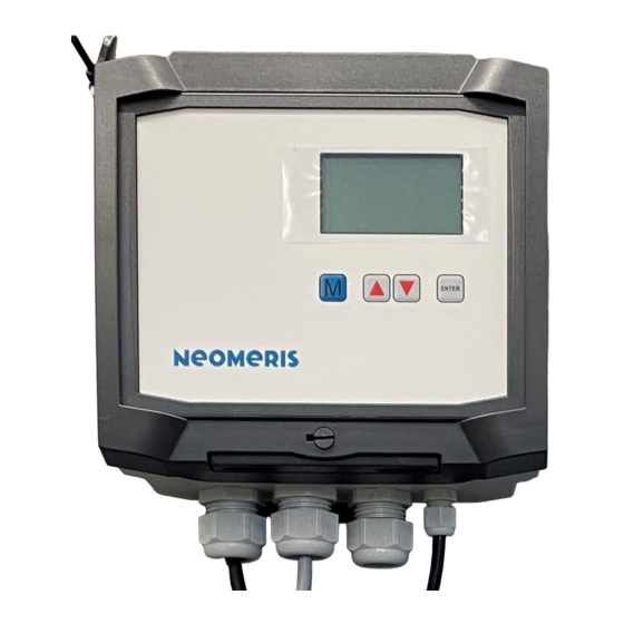
NEOMERIS CONTROL DES Specifications 4 Specifications 4.1 General characteristics 4.1.1 Housing The control unit is placed in the following housing: Type Bocard 160 high, gray/light gray Producer Bopla GmbH Size / Dimensions 199mm x 179mm x 106,5mm (WxDxH) Protection Class... -
Page 18: Digital Inputs
NEOMERIS CONTROL DES Specifications Information Voltage like incoming main supply max. Current 5A AC max. Power nom. 1100VA Remark reduced wit inductive load Description Supply sourcing 24V DC for externals Information Voltage 24V DC max. Current 600mA DC max. Power Remark 4.1.5 Digital Inputs... - Page 19 NEOMERIS CONTROL DES Specifications max. Switching Volt. 250V AC max. Switching Cur. 5A AC, Contact 6A max. Perm. Current 3A AC nom. Cycles see datasheet Component FTR, LYCA024V Remark Identifier Bleed off valve Information Bleed off valve Type Relay, change over contact, power switching max.
-
Page 20: Analog Inputs
NEOMERIS CONTROL DES Specifications 4.1.7 Analog Inputs The control unit has the following analogue inputs / measuring inputs: Identifier Cond. Probe (conductive) Information Type Conductivity, conductive sensor Range 0 ... 5000µS/cm Input Resistance Resolution 0.2% Accuracy Linearity Filter Tau = 1s Linearization Temperature compensation 2.2%/K... -
Page 21: Analog Outputs
NEOMERIS CONTROL DES Specifications 4.1.8 Analog Outputs The control unit has the following analog outputs: Identifier Get conductivity in mA Information Type Current Output Range 0 ... 20mA Input Resistance > 12V (under Load = 600 Ohm) max. Current 25mA Filter 1st order, fcut off = approx. - Page 22 NEOMERIS CONTROL DES Specifications Type Standard Specification EC Declaration of Conformity CE-Mark conform EMC Directive EMV 2014/30/EG conform Low Voltage Directive 2014/35/EG conform Standard EN 61000-6-2 applied Standard EN 61000-6-4 applied Standard EN ISO 12100-1 applied Standard EN ISO 12100-2...
-
Page 23: Views And Dimensional Drawings
NEOMERIS CONTROL DES Specifications 4.3 Views and dimensional drawings 4.3.1 Front film layout All information and technical data are subject to Page 16 Build:20211025-094624-9873335NSt change... -
Page 24: Housing Bottom And Drill Pattern
NEOMERIS CONTROL DES Specifications 4.3.2 Housing Bottom and Drill Pattern For mounting use the following pattern (measurements see marked line below) All information and technical data are subject to Page 17 Build:20211025-094624-9873335NSt change... -
Page 25: Installation
NEOMERIS CONTROL DES Installation 5 Installation 5.1 Preparing for installation For setup and installation, please refer to the existing plans and draw- ings as in chapter 4 "Specifications." NOTE We recommend interconnecting alerts with the control room. Ignoring WARNING or failing to acknowledge the fault over a longer period of time may lead to severe damage to the system or even a complete production down- time. -
Page 26: Installation Process
NEOMERIS CONTROL DES Installation ƒ It is imperative to ensure that the measuring and control lines are installed at a maximum distance to power cables. This will prevent undesirable irradiation. Keep connection lines as short as possible. ƒ Lay connection lines well away from the mains cable. - Page 27 NEOMERIS CONTROL DES Installation b. Working location c. Date d. Name of party responsible 3. For connection purposes, exclusively use tested lines with sufficient line cross-sections. A qualified electrician complying with VDE and EVU installation guidelines and company standards is required for performing electrical installations.
-
Page 29: Connectors (X) - Overview
NEOMERIS CONTROL DES Installation 5.4.2 Connectors (X) – overview Num. Model / Type Grid Type Wire el. Spec Clamps eB0.X1 MTA-156 3.96mm Print Connector 275V / 6A AC eB1.X1 MTA-156 3.96mm Print Connector 275V / 6A AC 5.4.3 Terminal block (TB) – overview... - Page 30 NEOMERIS CONTROL DES Installation eB1.TB2 Relay, normally close contact, isolated Operating Signal eB1.TB2 Relay, change over contact, isolated Operating Signal eB1.TB2 Relay, normally open contact, isolated Operating Signal eB1.TB2 Relay, normally close contact, isolated Alarm signal eB1.TB2 Relay, change over contact, isolated Alarm signal eB1.TB2...
-
Page 31: Input-/Output Schema
NEOMERIS CONTROL DES Installation 5.5 Input-/Output Schema The following diagram shows the adaption of the control unit. To avoid overlapping, some wires are displayed interrupted and dashed. All information and technical data are subject to Page 24 Build:20211025-094624-9873335NSt change... -
Page 32: Configuration/Jumper
NEOMERIS CONTROL DES Installation 5.6 Configuration/Jumper This chapter contains general information about configuring the hardware. Type / Usage used Jumper Selections Effect eB2.JP- Cond. eB2.JP1 Selection of the possible measuring range: Range Se- eB2.JP2 JP1=o JP2=o Depending on which measuring range you want to measure, the jumper must be lection plugged in accordingly. -
Page 33: Functional Description
Functional description 6 Functional description This chapter describes the structure and details of the control functions and their parameters. 6.1 System overview/-structure NEOMERIS CONTROL DES (System), DES_128 ƒ Device (MDesalDevice2Ext), Control Unit ƒ Data Transfer (MSDCard), Logging of remnant data ƒ... -
Page 34: Module: Mdesaldevice2Ext
NEOMERIS CONTROL DES Functional description Module: MDesalDevice2Ext 6.2.1 Info: Control Unit 6.2.2 Comment: This module forms the functional core of the control unit and contains all process-related functions and processes of the control, which are formed by the various (sub) function modules (s.b.). -
Page 35: Internal Elements Of Module
NEOMERIS CONTROL DES Functional description This module measures the flow rate in liters per hour. MTankAlarms: Tank with 2 alarms This module manages a tank with tank level sensors. MPumpPuls: Dosing pump This module controls a pump with pulse control. -
Page 36: Module: Mdesal2
NEOMERIS CONTROL DES Functional description Module: MDesal2 6.3.1 Info: Control of the desalting process 6.3.2 Comment: Control of the actual desalination. There are the following desal states : Off = manual forced-off selected or missing unlock On = manual forced-on selected... - Page 37 NEOMERIS CONTROL DES Functional description Range: 0 ... 5000 µS/cm Default: 2500 µS/cm Conductivity hysteresis for the desalination start Hysteresis (Num.) Range: 0 ... 5000 µS/cm Default: 20 µS/cm Reduction of the conductivity threshold before a time dosing Pre Bleed start (Num.) Range: 0 ...
-
Page 38: Module: Mdosprop
NEOMERIS CONTROL DES Functional description Module: MDosProp 6.4.1 Info: Quantitatively proportional dosing 6.4.2 Comment: The proportional dosing is responsible for the proportional addition of chemicals to the process wa- ter by a dosing pump. The dosing pump is controlled by pulses generated by the flow meter. - Page 39 NEOMERIS CONTROL DES Functional description Range: 0.00 ... 9.99 s Default: 0.25 s Period duration of proportional dosing output impuls High duration (Num.) Range: 0.00 ... 9.99 s Default: 0.25 s Limit of stored impulses Pulse limit (Num.) Range: 0 ... 99999999...
-
Page 40: Module: Mdostime
NEOMERIS CONTROL DES Functional description Module: MDosTime 6.5.1 Info: Time dosage 6.5.2 Comment: Time Dosing (Typically Biocide Dosing) . There are four start times settable for the time dosing (Parameter: Start time / Wochentage). The set time always has priority over the current conductivity value. - Page 41 NEOMERIS CONTROL DES Functional description Range: 0 ... 999 min Default: 15 min Max. possible dosing time per day Total Time (Num.) Range: 0 ... 999 min Default: 0 min All information and technical data are subject to Page 34...
-
Page 42: Module: Munlock
NEOMERIS CONTROL DES Functional description Module: MUnlock 6.6.1 Info: System enable 6.6.2 Comment: The switching input must be active (s.b.) for the plant to start operation. The contact type can be freely selected. When (occupied = active), closing the input activates the operation. When (occu- pied = inactive), opening the input will activate the operation. -
Page 43: Module: Munianaoutext
NEOMERIS CONTROL DES Functional description Module: MUniAnaOutExt 6.7.1 Info: Analog Outp. 6.7.2 Comment: Based on the determined conductivity value of the process water, a corresponding current is out- put. This current can be between 0mA to 20mA or 4mA to 20mA depending on the set range. - Page 44 NEOMERIS CONTROL DES Functional description Output range: 0.00 ... 20.00 mA All information and technical data are subject to Page 37 Build:20211025-094624-9873335NSt change...
-
Page 45: Module: Moptime
NEOMERIS CONTROL DES Functional description Module: MOpTime 6.8.1 Info: Operating Time 6.8.2 Comment: Counts the operating hours of the plant and stores them in permanent memory. 6.8.3 Internal elements of module: This module contains no elements. All information and technical data are subject to... -
Page 46: Module: Mdelpump
NEOMERIS CONTROL DES Functional description Module: MDelPump 6.9.1 Info: Pump Relay 6.9.2 Comment: The pump has an adjustable start-up delay of 15 seconds by default (parameter: switch-on delay). The pump is always energized as long as the desalination is active or the desalination mode is ei- ther process-controlled or on. -
Page 47: Module: Mabsconductivitycomptemp
NEOMERIS CONTROL DES Functional description 6.10 Module: MAbsConductivityCompTemp 6.10.1 Info: Sensor Conduct. 6.10.2 Comment: Measures the conductivity of the process water. Due to the determined temperature of the temperature sensor, a temperature compensation can take place. There are three ways to compensate for the conductivity value: 1. - Page 48 NEOMERIS CONTROL DES Functional description Range: 0 ... 5000 µS/cm Default: 50 µS/cm Alarm low limit »Min(Alarm) (Num.) Range: 0 ... 5000 µS/cm Default: 25 µS/cm Warning high limit »Max(Warn.) (Num.) Range: 0 ... 5000 µS/cm Default: 2800 µS/cm Alarm high limit »Max(Alarm) (Num.)
- Page 49 NEOMERIS CONTROL DES Functional description 6.10.3.2 Analog input (AI) eB2: 11=PE, 12=LF, 13=0V (Conductance Input »Cond. conductive Input range: 0 ... 5000 µS/cm eB2: 5=24V, 6=D1, 7=0V (Analog-Input 1 (with supply)) »Cond. inductive Input range: 0 ... 5000 µS/cm 6.10.3.3 Analog output (AO) LF-Measuring Voltage »LF-Mess.Voltage...
-
Page 50: Module: Mtemperature
NEOMERIS CONTROL DES Functional description 6.11 Module: MTemperature 6.11.1 Info: Temp. Sensor 6.11.2 Comment: The temperature sensor measures the temperature in a range of 0.0 to 99.9 ° C. 6.11.3 Internal elements of module: 6.11.3.1 Parameters Warning low limit »Min(Warn.) (Num.) Range: 0.0 ... - Page 51 NEOMERIS CONTROL DES Functional description Reaction of the system to an alarm-type mes- sage Default: Continue 0 Continue No shutdown Shutdown with permanent re- »Reac. Sys. (Sel.) 1 Shutdown tries Cycl.shut- Shutdown with defined number down of retries Dur. shut-...
-
Page 52: Module: Mflowmeter2
NEOMERIS CONTROL DES Functional description 6.12 Module: MFlowMeter2 6.12.1 Info: Flow Meter 6.12.2 Comment: The flow meter measures the flow rate in liters per hour and is generating the appropriate pulses for the measured flow rate. The incoming pulses from the flow meter are counted and output pulses are generated depending on the pulse ratio (parameter: pulse ratio). -
Page 53: Internal Elements Of Module
NEOMERIS CONTROL DES Functional description It is therefore strongly recommended that min. flow should be set to logical values. Simply set to 1 will lead to a bad behavior of the measurement. Max flow is the maximum flow that must be measured correctly. - Page 54 NEOMERIS CONTROL DES Functional description Measuring method(process controlled, pulscount or pulslength) Default: Counter Mesrg. Method (Sel.) 0 Automatic 1 Counter Puls Length Time periode for counting of impulses Gate Time (Num.) Range: 0 ... 9999999 ms Default: 1000 ms Stabilisation time of impuls Debounce (Num.)
- Page 55 NEOMERIS CONTROL DES Functional description Range: 0 ... 999 s Default: Reaction of the system to an alarm-type mes- sage Default: Continue 0 Continue No shutdown Shutdown with permanent re- »Reac. Sys. (Sel.) 1 Shutdown tries Cycl.shut- Shutdown with defined number...
-
Page 56: Module: Mtankalarms
NEOMERIS CONTROL DES Functional description 6.13 Module: MTankAlarms 6.13.1 Info: Tank using 2 Alarms 6.13.2 Comment: The controller can manage a tank with one or two sensors. For the tank level sensor full or low, the contact type (occupied / n.occupied) can be set. - Page 57 NEOMERIS CONTROL DES Functional description All information and technical data are subject to Page 50 Build:20211025-094624-9873335NSt change...
-
Page 58: Module: Mpumppuls
NEOMERIS CONTROL DES Functional description 6.14 Module: MPumpPuls 6.14.1 Info: Pump 6.14.2 Comment: Pump with pulse control. Usually used as a dosing pump in conjunction with a flow meter, as the flow meter generates pulses that can be processed this way. -
Page 59: Module: Mstartdata
NEOMERIS CONTROL DES Functional description 6.15 Module: MStartData 6.15.1 Info: Dataset for time dosing 6.15.2 Comment: By setting the start time and the corresponding days of the week, a record is created according to the time metering. This record is compared to the current time. -
Page 60: Module: Malarmmgrdos
NEOMERIS CONTROL DES Functional description 6.16 Module: MAlarmMgrDOs 6.16.1 Info: Alarm-Manager + DO's 6.16.2 Comment: Alarm Manager Module which detects alerts and alarms of each module. This allows the system to respond to warnings or alarms as follows: - No shutdown: The system reports the error but continues to run normally. -
Page 61: Module: Mprotocolsdccsv
NEOMERIS CONTROL DES Functional description 6.17 Module: MProtocolSdcCsv 6.17.1 Info: Protocol 6.17.2 Comment: Ein Header wird erstellt und in die Datei geschrieben. Die Kopfzeile enthält die Elementnamen und Einheiten der Werte. Die CSV-Datei hat die folgenden Kategorien: 1. Systemdatum der Aufzeichnung 2. - Page 62 NEOMERIS CONTROL DES Functional description All information and technical data are subject to Page 55 Build:20211025-094624-9873335NSt change...
-
Page 63: Operation
NEOMERIS CONTROL DES Operation 7 Operation 7.1 Operating and Display Elements The user interfaces is arranged as follows: 7.2 Navigation and Programming 7.2.1 General information Use keyboard and display for programming the control system. Incorrect programming may lead to a failure of crucial controller... -
Page 64: Automatic Reset
NEOMERIS CONTROL DES Operation If you are entering parameters, pressing <Enter> will cause the cursor to move one position further right. If you are changing parameters, use the arrow keys to select the requested digit and then press <Enter> to confirm. Select all the parameters to apply the values. -
Page 65: Configuration Of Modules / Functions
NEOMERIS CONTROL DES Operation 7.3 Configuration of modules / functions If this menu exists, it is possible to disable unneeded / wanted modules / functions. This is done in a configuration menu. In this menu all disconnectable modules / functions are listed. -
Page 66: Type Of Contact Or Inversion
NEOMERIS CONTROL DES Operation 7.4 Type of contact or inversion It is possible to invert the type of contact (NC / NO) of the connected sensors or buttons / switches. The following shown masks contains exemplary elements/chan- nels, which are currently not existing in this present control unit. -
Page 67: Calibration
NEOMERIS CONTROL DES Operation 7.5 Calibration To compensate for measurement errors due to deviations in sensors and measuring amplifiers, the analog inputs and outputs can be calibrated using reference measurements. In this case, the value of a lower and an upper known reference variable is “assigned” (learned) and interpolated linearly between these points (if necessary, there is an additional compensation / linearization). - Page 68 NEOMERIS CONTROL DES Operation The current assignment appears: The current temperature Act: 24.7 °C is assigned to a converter value of 00583. Press the Ï key to enter the upper point. (Press Ð to enter the lower point.) Change the value with the keys Ï or Ð, with Enter a digit is moved to the right. After entering the value, exit the mask with Enter.
-
Page 69: Analog Output
NEOMERIS CONTROL DES Operation 7.5.2 Analog Output Similar to the input calibration, the output calibration takes place. In the channel list it is possible to force the output value via the -keys while inside the calibration. Ï/Ð All information and technical data are subject to... -
Page 70: Diagnostics
NEOMERIS CONTROL DES Operation 7.6 Diagnostics The hardware diagnostics allow the direct manipulation or representation of the outputs and inputs of the control unit. The following shown masks contains examplary elements/chan- nels, which are currently not existing in this present control unit. -
Page 71: Alarm Handling And Messages
NEOMERIS CONTROL DES Operation 7.7 Alarm Handling and Messages The control unit has an alarm manager. The operating errors are detected by the control unit and displayed as a text message. The messages of the alarm manager can be reached via the menu of the control unit. -
Page 79: Anhang
Default: NEOMERIS CONTROL DES, Device, Data 0 TAB Transfer Time interval at which the records are executed »Record. Interval (Num.) NEOMERIS CONTROL DES, Device, Data Ac- Range: 0 ... 999 min quisition Default: 1 min Time interval between the generation of new »New file-interval (Num.) - Page 80 Type of control of the bleed off valve Default: Process contr. Bleed off mode (Sel.) 0 Process contr. control according process NEOMERIS CONTROL DES, Device, Bleed off 1 Off Always off 2 On Always on Conductivity threshold above which the desali- nation starts Bleed off start (Num.)
- Page 81 NEOMERIS CONTROL DES Appendix Warning low limit »Min(Warn.) (Num.) NEOMERIS CONTROL DES, Device, Bleed Range: 0 ... 5000 µS/cm off, Conductivity Sensor Default: 50 µS/cm Alarm low limit »Min(Alarm) (Num.) NEOMERIS CONTROL DES, Device, Bleed Range: 0 ... 5000 µS/cm...
- Page 82 NEOMERIS CONTROL DES Appendix »Min(Warn.) (Num.) Range: 0.0 ... 99.9 °C NEOMERIS CONTROL DES, Device, Bleed Default: 10.0 °C off, Conductivity Sensor, Temp.Sensor Alarm low limit »Min(Alarm) (Num.) NEOMERIS CONTROL DES, Device, Bleed Range: 0.0 ... 99.9 °C off, Conductivity Sensor, Temp.Sensor Default: 3.0 °C...
- Page 83 NEOMERIS CONTROL DES Appendix active=ener- »Contact Type (Sel.) gized NEOMERIS CONTROL DES, Device, Bleed active=not en- off, Bleedoff Valve Control ergized Measuring resolution of water amount (impuls Measure Res. (Num.) per liter) NEOMERIS CONTROL DES, Device, Bleed Range: 0.001 ... 999.999 pls/Ltr off, Blowd.
- Page 84 NEOMERIS CONTROL DES Appendix »Max(Warn.) (Num.) Range: 0 ... 32767 l/h NEOMERIS CONTROL DES, Device, Bleed Default: 900 l/h off, Blowd. flow Alarm high limit »Max(Alarm) (Num.) NEOMERIS CONTROL DES, Device, Bleed Range: 0 ... 32767 l/h off, Blowd. flow...
- Page 85 NEOMERIS CONTROL DES Appendix Pause duration between 2 pulses of prop. dos- Low duration (Num.) ing output NEOMERIS CONTROL DES, Device, Prop. Range: 0.00 ... 9.99 s dosing 1 Default: 0.25 s Period duration of proportional dosing output im- High duration (Num.) puls NEOMERIS CONTROL DES, Device, Prop.
- Page 86 Reaction of the system to an alarm-type mes- sage Default: Continue 0 Continue No shutdown Reac. Sys. (Sel.) NEOMERIS CONTROL DES, Device, Prop. Shutdown with permanent re- 1 Shutdown dosing 1, Tank prop. Dos. 1, Alarm empty tries Shutdown with defined num- 2 Cycl.shutdown ber of retries 3 Dur.
- Page 87 5 Friday Friday 6 Saturday Saturday Kind of contact (pulled/released) Default: active=energized »Contact Type (Sel.) active=ener- NEOMERIS CONTROL DES, Device, Time gized Dosing 1, Dosing Valve 1 active=not en- ergized Kind of contact (used/n.used) Default: not occupied=active »Contact Type (Sel.)
- Page 88 NEOMERIS CONTROL DES Appendix active=not en- ergized All information and technical data are subject to Page 81 Build:20211025-094624-9873335NSt change...
-
Page 89: Maintenance And Repair
NEOMERIS CONTROL DES Appendix 8.2 Maintenance and Repair NOTE To ensure the perfect function of the control unit a regular maintenance is necessary (six- monthly, annual)! ƒ clean up the sensor, especially the electrodes check if the sensors are still water-proof ƒ... -
Page 90: Software Update, Change Firmware
NEOMERIS CONTROL DES Appendix 8.3 Software Update, change Firmware You can use the device with different software to run a variety of controlling jobs with varied types of behaviour. Ensure that the cor- WARNING rect software is installed. An update can enhance an existing software or giving the control unit a complete new functional- ity/usage. -
Page 91: Pc-Software
NEOMERIS CONTROL DES Appendix 8.4 PC-Software 8.4.1 Obtaining the software and drivers You will find the suitable software and possibly required drivers at the following web address: www.heylneomeris.de/mediathek/software/ 8.4.2 Requirements / Installation For "installation" on a PC (Windows 7 or higher), the PC software ZIP file associated with the de- vice with the corresponding revision of the previously mentioned web address must be unpacked onto a data carrier of the PC. -
Page 95: Ec-Declaration Of Conformity
NEOMERIS CONTROL DES Appendix 8.6 EC-Declaration of Conformity See next page. All information and technical data are subject to Page 88 Build:20211025-094624-9873335NSt change...
Need help?
Do you have a question about the CONTROL DES and is the answer not in the manual?
Questions and answers