Table of Contents
Advertisement
5F/H, 05FY/HY, 06D/E, 07D/07E series water cooled condensing units are custom made.
Each unit contains UL certified components, the assembly of each unit is not UL, ETL, or CSA recognized.
CONTENTS
SAFETY CONSIDERATIONS. . . . . . . . . . . . . . . . . . . . . . 1
INSTALLATION . . . . . . . . . . . . . . . . . . . . . . . . . . . . . . . . 1-6
Receive and Inspect Unit . . . . . . . . . . . . . . . . . . . . . . . . . 1
Place Unit in Position . . . . . . . . . . . . . . . . . . . . . . . . . . . . 1
Check Compressor Mounting . . . . . . . . . . . . . . . . . . . . 1
Piping Connections . . . . . . . . . . . . . . . . . . . . . . . . . . . . . . 2
Electrical Connections . . . . . . . . . . . . . . . . . . . . . . . . . . . 2
PRE-START-UP . . . . . . . . . . . . . . . . . . . . . . . . . . . . . . . . .7,8
Evacuate, Dehydrate, and Leak Test . . . . . . . . . . . . . 7
Oil Charge . . . . . . . . . . . . . . . . . . . . . . . . . . . . . . . . . . . . . . . 7
START-UP . . . . . . . . . . . . . . . . . . . . . . . . . . . . . . . . . . . . . . . 8
Start Compressor . . . . . . . . . . . . . . . . . . . . . . . . . . . . . . . . 8
Timer Functions . . . . . . . . . . . . . . . . . . . . . . . . . . . . . . . . . 8
SERVICE . . . . . . . . . . . . . . . . . . . . . . . . . . . . . . . . . . . . . . 9-18
Protection Devices . . . . . . . . . . . . . . . . . . . . . . . . . . . . . . . 9
Compressor Thermal Protection . . . . . . . . . . . . . . . . . 9
Capacity Control System. . . . . . . . . . . . . . . . . . . . . . . . . 9
Components . . . . . . . . . . . . . . . . . . . . . . . . . . . . . . . . . . 10
Lubrication System . . . . . . . . . . . . . . . . . . . . . . . . . . . . . 13
Cylinder Heads. . . . . . . . . . . . . . . . . . . . . . . . . . . . . . . . . . 14
Pressure Relief Valve . . . . . . . . . . . . . . . . . . . . . . . . . . . 14
Terminal Plate Assembly. . . . . . . . . . . . . . . . . . . . . . . . 14
Compressor Running Gear Removal . . . . . . . . . . . . 14
Compressor Running Gear Replacement . . . . . . . 15
Motor Removal . . . . . . . . . . . . . . . . . . . . . . . . . . . . . . . . . . 16
Motor Replacement . . . . . . . . . . . . . . . . . . . . . . . . . . . . . 16
Motor Burnout (Clean-Up Procedure) . . . . . . . . . . . 17
Condenser Maintenance . . . . . . . . . . . . . . . . . . . . . . . . 17
SAFETY CONSIDERATIONS
Installing, starting up, and servicing this equipment can be
hazardous due to system pressures, electrical components, and
equipment location (roofs, elevated structures, etc.). Only
trained, qualified installers and service mechanics should
install, start up, and service this equipment.
When working on the equipment, observe precautions in the
literature, tags, stickers and labels attached to the equipment,
and other safety precautions that apply. Follow all safety codes.
Wear safety glasses and work gloves. Use care when handling,
rigging, and setting bulky equipment.
Electrical shock can cause personal injury and even death.
Be sure power to equipment is shut off before installing or
servicing this equipment. There may be more than one dis-
connect. Tag disconnect(s) to alert others not to turn power
on until work is completed.
Manufacturer reserves the right to discontinue, or change at any time, specifications or designs without notice and without incurring obligations.
Book 2
2
4
4
PC 802
Tab 1b 2a 2b 3a
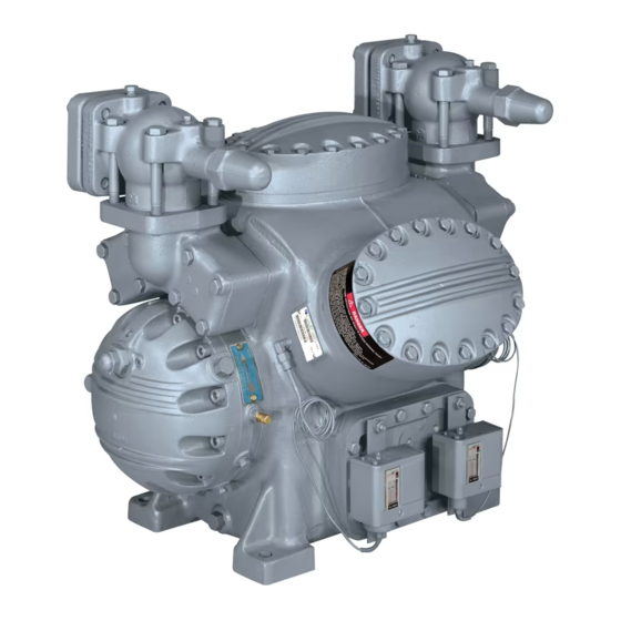
Compressors and Condensing Units
Installation, Start-Up and
Service Instructions
Hermetic, Water-Cooled
Page
Catalog No. 530-607
Printed in U.S.A.
INSTALLATION
Receive and Inspect Unit -
damage. File claim with the shipping company if shipment is
damaged or parts are missing.
Local water conditions can cause excessive fouling or
pitting of condenser tubes. If such conditions are anticipated, a
water treatment analysis is recommended. Refer to Carrier
System Design Manual, Part 5, for general water conditioning
information.
Place Unit in Position -
well-ventilated area. Install unit where it will be warmer than
conditioned area. Position it to allow sufficient space for refrig-
erant and water connections and to service compressor. Allow
space at one end of condenser for tube cleaning or replacement.
Place unit so suction and discharge valves can be easily
reached and so oil level can be checked.
Make provision in piping layout to drain and vent condenser
if system is to be shut down in winter.
Level unit and bolt firmly to foundation.
Check Compressor Mounting -
sor mounting bolts and remove shipping blocks from under
compressor. Tighten all 4 bolts on compressor. Loosen each
bolt just enough until the flanged washer can be moved
sideways with finger pressure. See Fig. 1.
NOTE: Be sure that compressor floats freely on mounting
springs.
SELF-LOCKING
BOLT
Fig. 1 - Compressor Mounting
Form 06/07E-2SI Rev.A
Pg 1
06E,07E
Inspect shipment for
Locate unit on floor in a
Loosen compres-
SNUBBER FLANGED
WASHER
NEOPRENE
SNUBBER
COMPRESSOR FOOT
ISOLATION SPRING
11-21
Replaces: 06/07E-1SI
Advertisement
Table of Contents

Related Manuals for Carrier 5F/H Series


Summary of Contents for Carrier 5F/H Series
-
Page 1: Table Of Contents
Check Compressor Mounting ....1 water treatment analysis is recommended. Refer to Carrier Piping Connections ......2 System Design Manual, Part 5, for general water conditioning Electrical Connections . -
Page 2: Piping Connections
Allowing the unit to operate with a voltage Most local codes require piping from valve to outdoors. imbalance in excess of 2% may void the warranty. Refer to Carrier System Design Manual for standard piping techniques. POWER SUPPLY — Field wiring must comply with local Electrical Connections and national codes. - Page 4 NOTES: 1. For standard service practices, such as troubleshooting and refrigerant charging, allow a minimum 2-6 clearance around the unit. 2. For compressor removal, allow a minimum 3 wide access aisle to and from the unit. 3. Local codes or jurisdiction may prevail for unit clearances. DIMENSIONS (in.) 06E UNIT VOLTAGE...
- Page 5 7. Electrical data for compressor part numbers 06ER, 06EM and 3. 3-Pole XL circuit breakers shown, other 3-Pole XL alternates 50 Hz models (not shown) are available from Carrier Sales and 6-Pole PW breakers available. Terminal lugs for circuit Representative.
- Page 6 LEGEND AUX — Auxiliary — Evaporator Fan or Terminal Block Connector — Compressor Contactor Chilled Water Pump — Compressor Contactor — Cooling Tower Pump (XL start and first step of PW start) — Cooling Tower Fan Unmarked Terminal — Compressor Contactor NEC —...
-
Page 7: Pre-Start-Up
To add or remove oil, see Carrier Standard Service PRE-START-UP Techniques Manual, Chapter 1, Refrigerants. IMPORTANT: Use only Carrier approved compressor oil. Do not reuse oil that has been drained and do not use oil When charging, or when removing charge, circulate water that has been exposed to atmosphere. -
Page 8: Start-Up
After about 20 minutes of operation, stop the com- pressor. Allow it to be idle for about 5 minutes, then observe the oil level in the sight glass. Refer to the Carrier Standard Service Techniques Manual, Chapter 1, Section 1-11, for adding oil. -
Page 9: Service
exceeds 295 ± 5 F, the sensor contacts open and the compressor SERVICE shuts down. The sensor reset temperature is 235 F minimum. Protection Devices See Fig. 8 for control circuit connections. HIGH-PRESSURE SWITCH — Check by throttling con- Capacity Control System denser water or blocking airflow on air-cooled units, allowing CAPACITY CONTROL VALVE (Fig. -
Page 10: Removing, Inspecting And Replacing
Loaded — When suction pressure rises high enough to over- assemblies. For replacement items use Carrier Specified come control set point spring, the diaphragm snaps to the left Parts. and relieves pressure against the poppet valve. The drive spring 2. - Page 11 NOTE: Pressure-operated control valve shown. A solenoid-operated control valve can also be used. Fig. 10 — Suction Cutoff Unloader Operation...
- Page 12 15 16 17 18 LEGEND 17 — Oil Sight Glass Screw 32 — Valve Plate Assembly (includes dis- 1 — Stator (Compressor Motor) 18 — Oil Sight Glass Lock Washer charge valves) 2 — Rotor (Compressor Motor) 19 — Pipe Plug (Hex Head) 33 —...
-
Page 13: Lubrication System
Table 6 — Torque Values REMOVE 8 CAP SCREWS SIZE TORQUE THREADS DIAM RANGE USAGE PER IN. (in.) (lb-ft) 27 (pipe) 8-12 Pipe Plug — Crankshaft 18 (pipe) 20-25 Pipe Plug — Crankcase 8-10 Conn. Rod Cap Screw 8-12 Junction Box Sight Glass 14-18 Oil Pump Drive Segment... -
Page 14: Cylinder Heads
Keep each connecting rod and piston assembly together for Cylinder Heads (See Fig. 11) — Disassemble cyl- proper reassembly. Check all parts and crankpins for wear inder heads by removing cap screws, and prying up on side (refer to Table 7 for wear limits). lifting tabs to break heads loose from valve plates. -
Page 15: Compressor Running Gear Replacement
Compressor Running Gear Replacement CRANKSHAFT — Be sure compressor end bearing washer is in place on dowel pin. Install crankshaft through pump end, carefully guiding it through main bearings. Replace rotor. CRANKSHAFT CONNECTING ROD/PISTON ASSEMBLY (Fig. 18) — The assembly of the connecting rod with contoured-crown piston CONNECTING must be as shown. -
Page 16: Motor Removal
Push stator into housing until it lines up correctly with rotor DOWELS IN (Fig. 22). CYLINDER DECK DOWEL FOR SUCTION HOLES Line up keyways in stator and crankcase and replace stator VALVE AND BACKER DOWEL locking assembly, then drive key into keyway and stake over HOLES keyway in stator to secure key. -
Page 17: Motor Burnout (Clean-Up Procedure)
If such conditions are anticipated, water treatment chips.) Back off locking pin bushing of a turn. analysis is recommended. Refer to the Carrier System Design 4. Tap locking pin into position. (Top of bushing should be Manual, Part 5, for general water conditioning information. - Page 18 CENTRIFUGAL PUMP 1/2 HP CLOSE VENT PIPE FILL CONDENSER WITH GAS VENT 30 GPM AT 35’ HEAD VALVE WHEN CLEANING SOLUTION. DO PUMP IS PRIMING NOT ADD SOLUTION GLOBE PUMP RUNNING CONN. MORE RAPIDLY THAN VALVES VENT CAN EXHAUST SUCTION GASES CAUSED BY CHEMICAL ACTION.
- Page 20 © 2021 Carrier Manufacturer reserves the right to discontinue, or change at any time, specifications or designs without notice and without incurring obligations. Book 2 PC 802 Catalog No. 530-607 Printed in U.S.A. Form 06/07E-2SI Rev. A Pg 20 11-21...
Need help?
Do you have a question about the 5F/H Series and is the answer not in the manual?
Questions and answers