Table of Contents
Advertisement
Quick Links
Advertisement
Table of Contents

Related Manuals for IPC ST-35IPC

Summary of Contents for IPC ST-35IPC
- Page 1 IP camera tester User Manual (V01.00)...
- Page 2 Thank you for purchasing the IP camera tester. Please read the manual before using the IP camera tester and use properly. For using the IP camera tester safely, please first read the「Safety Information」carefully in the manual. The manual should be kept well in case of reference. Keep the S/N label for after-sale service within warranty period.
-
Page 3: Table Of Contents
Content 1 .Safety information ..........................1 2. IP Camera Tester Introduction ......................2 2.1 General ............................2 2.2 Packing list ..........................2 2.3 Function interface ........................3 3. Operation ............................. 5 3.1 Installing the Battery ........................5 3.2 Instrument connection ........................ 6 3.2.1 IP camera connection ...................... - Page 4 (2)IP address scan ......................42 (3)Network test (Ethernet bandwidth test) ................ 43 (4)Port Flashing ........................ 46 (5)DHCP server ........................ 47 (6)Trace route ........................48 (7)Link monitor ........................ 49 3.3.14 Rapid IP Discovery ..................... 49 3.3.15 Audio Record ......................50 3.3.16 Data monitor ....................... 50 3.3.17 Audio player ........................
-
Page 5: Safety Information
1 .Safety information ◆ The tester is intended to use in compliance with the local rules of the electrical usage and avoid to apply at the places which are inapplicable for the use of electrics such as hospital, gas station etc. ◆... -
Page 6: Ip Camera Tester Introduction
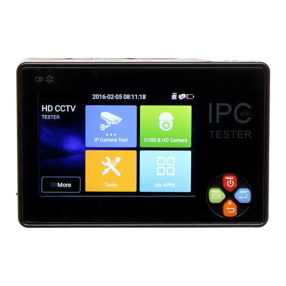
2. IP Camera Tester Introduction 2.1 General The 3.5 inch IPS touch screen IP camera monitor is designed for maintenance and installation of IP cameras, analog cameras,TVI, CVI AHD cameras, as well as testing 4K H.264 /4k H.265 camera by mainstream, The 480x320 resolution enables it to display network HD cameras and analog cameras in high resolution. -
Page 7: Function Interface
2.3 Function interface The charge indicator: it lights red while the battery is being charged. As the charging is complete, the indicator turns off automatically The RS485 data transmission indicator: it lights red while the data is being transmitted Press more than 2 seconds, turn on or off the device ,short press to turn on or off the menu display Confirm key /zoom key Return/Close : Return or cancel while setting parameters of the menu, close or... - Page 8 Top interface Left interface Right interface Bottom interface Video signal input(BNC interface)/ AHD,CVI and TVI input (BNC interface) DC5V1.5A USB charging interface Page.4.
-
Page 9: Operation
DC12V1A power output , for provisional DC power supply RS485 Interface: RS485communication for the PTZ Audio input Battery slot Lan port Micro SD card moveable (supports up to 32GB) 3. Operation 3.1 Installing the Battery The tester has built-in lithium ion polymer rechargeable battery. The battery cable inside battery cabin should be disconnected for safety during transportation! Prior to the use of the instrument, the battery cables inside the battery cabin should be well connected. -
Page 10: Instrument Connection
LAN port, if the link indicator of the tester’s LAN port is green and the data indicator flickers, it means the IP camera and the IPC tester are communicating. If the two indicators don’t flicker, check if the IP camera is powered on or the network cable is not functioning properly. -
Page 11: Analog Camera Connection
Warning: Poe switch or PSE power sourcing equipment only can be connected to tester “PSE IN” port, otherwise will damage the tester. 3.2.2 Analog camera connection (1) Connect the camera's video output to the IP tester’s VIDEO IN. The image will display on the tester after pushing the PTZ icon (2) CCTV IP Tester “VIDEO OUT”... -
Page 12: Osd Menu
(1) Connect the CVI camera's video output to the IP tester’s “Video IN” interface, the image will display on the tester. The tester only come with CVI input interface. There is no CVI output interface. (2) Connect the CVI camera or the speed dome RS485 controller cable to the tester RS485 interface. 3.3 OSD menu ◼... -
Page 13: Drop-Down Menu
◼ In Lite mode, Press the icon several seconds, can move the icon to other apps ◼ In lite mode, click the finger icon in the lower right corner to release lock icon, move icons and change function icons sequence. Click SD card, install or remove SD card. -
Page 14: Screen Capture
CVBS: Click icon “CVBS “to enter, you can test IP and analog camera at the same time. LAN: Display network port or WIFI connection real-time upload and download speeds and other network parameters. Settings: Enter settings interface. IP: Enter IP Settings interface. 3.3.3 Screen capture long press the key “enter”, can capture screen interface and save it in any time. - Page 15 The meter creates WIFI hotspot, connect mobile phone to the tester’s WIFI hotspot, or the tester and mobile phone connect to the same Wi-fi network. Tap icon “ ”, then select “TesterPlay” app to enter, click “Start” button to generates two-dimensional code, Please use mobile phone scan it, then download and install the client software, you can view the screen real-time projection.
-
Page 16: Rapid Video
video 3.3.5 Rapid Press enter function, One key to detect all network cameras and auto play the images. Auto log in and display camera image. Detailed operation refer to ONVIF function Page.12. -
Page 17: Ip Discovery
After exit ONVIF app, Click Refresh to search ip address. 3.3.6 IP discovery Press IP discovery ,tester auto-scan the whole network segment IP, as well as auto-modify the tester‘s IP to the same network segment with the scanned camera's IP. Tester’s IP address, Tester can auto-modify the tester‘s IP to the same network segment with Local IP: the scanned camera's IP... -
Page 18: Rapid Onvif Test
Rapid ONVIF: Rapid ONVIF Quick link IPC TEST: IPC TEST Quick link Using IP discovery app ,you don’t need to know the first two digits of camera’s IP Applicability: address , it can auto-scan the whole network segment IP, and auto-modify tester’s IP address , greatly improved engineering efficiency 3.3.7 Rapid ONVIF test... - Page 19 Click the button “Refresh”, tester will scan the ONVIF camera again. Click the newly displayed ONVIF camera on the “Device List“. The tester will show the IP camera’s relative information and settings. Activate HIKVISION Camera: When connected unactivated HIKVISION Camera, tester can auto recognized ,And prompt "The camera is not active, you need to activate it", click "OK"...
- Page 20 When comes out “activate success” prompt, click login to display camera image. Pop-up settings menu when click the “ONVIF setting ”icon in the upper left corner Page.16.
- Page 21 Across network segments scan: After open this function , enter “Setting”-“IP Settings”-“Advanced”to add other network segments IP, Rapid ONVIF function can across network segments to scan camera’s Auto Login : After open this function, tester can auto login camera and display camera image (The login password is the same with last time, the first time using password is the default password "admin") Video transmission protocol: UTP and TCP protocol...
- Page 22 ONVIF PTZ control: Tap the image in the direction you want the PTZ camera to move. Tap the left side of the image to move left, right to go right, up to go up and down to go down. Compatible IP PTZ cameras will rotate accordingly.
- Page 23 Image setting: Click “Imaging Set” to adjust image brightness, saturation, contrast, sharpness and backlight compensation mode. Profiles:Click “profiles",can view video streaming current configuration files, as well as switch between Major stream and minor stream . Preview pictures:Quickly preview and zoom in or out pictures, automatically and manual refresh Page.19.
- Page 24 Identification: click “Identification” to view information of the camera Time set: click “Time set”, Select " Manual set" to set up the time of camera Maintenance: For camera software reset or restore to factory settings. Page.20.
- Page 25 User Set: Modify camera user name ,password etc parameters Network setting:Click “Network Set “to change the IP address. Some cameras cannot support change IP address, so there is no change after saving. Zoom in image :press the key to enter the zoom mode. Press it again to exit zoom mode.When the image is enlarged tap left, right, up or down on the image to move the whole image on the screen Page.21.
- Page 26 If it is network video input to the tester, as the tester supports resolution up to 1080p, the input image will be very clear after it is enlarged. This is greatly helpful for the installers to ensure the IP camera’s video coverage and decide the IP camera’s install site.
- Page 27 Playback:Click the “Playback” icon to view saved videos. Double click the video you want to play. Click to return to the last menu To rename or delete a photo, click and hold on the file until this screen appears: Video files can play in the Video player on the main menu. Set preset position :Move the camera to preset position, enter the preset number on the Bottom right corner to complete position preset.
- Page 28 PTZ Speed set : Horizontal and Vertical Speed set RTSP: Get RTSP address of the current camera Doc: Auto generate test reports document of camera, click "Create document”. Click Preview to view the report document Page.24.
- Page 29 Enter the camera test information, click "Create Document" to complete the report. click doc menu again, you can preview the report document. Page.25.
-
Page 30: Ip Camera Test
Click icon to enter IP camera test Note: Currently, the IPC Test App only supports some brands’ specific IP cameras,these include specific models made by ACTI, AXIS, Dahua, Hikvision, Samsung, and many more. If the camera is not fully integrated, please use the ONVIF or RTSP apps. - Page 31 IP address. If the tester is connected to a PoE switch, it will find and display several IP address IPC User Name: Enter IP camera’s user name IPC Password: Enter IP camera’s login password IPC Port :: When you select the IP camera type, it will default the camera’s port number and doesn’t Page.27.
-
Page 32: Video Monitor Test
IP camera test interface. Once you are viewing video on the IPC Test app, you will see the “Video Menu” icon on the top right. This button will give you access to Snapshot, Record, Photo, Playback, PTZ, and Set. Please refer to the ONVIF section to use these functions. - Page 33 Display the input video image, click the top menu bar icon to enter video level meter, (PEAK level, SYNC level, COLOR BURST measurement) Select relative function on the right side Toolbar to operate , functions including “Photos”, “Snapshot” , “Record” , “Playback” , “PTZ” , “Set” , Click the screen twice quickly, can be full zoom in on the touch screen.
- Page 34 Check and set the protocols, address, interface and baud, all must be consistent with the dome camera, then the IPC tester can test .After setting the parameter, the tester can control the PTZ and lens To control PTZ by screen touch: Tap left, right, upward and downward on the touch screen to control the PTZ rotation direction.
- Page 35 (3) 4 x zoom image display and Video out to enter “zoom”, press it again to quit. When image input, press Using the touch screen to control PTZ camera movement: Tap left, right, upward or downward on the video image to move the PTZ camera in a desired direction. Stretch two fingers outward or inward on the touch screen to zoom the image in or out.
- Page 36 (5) Video record When you click the “Record” icon, video starts recording. A red recording icon appears on the screen and begins to flash and a timer appears indicating the time elapsed for the video. Click on the “Record” icon again to stop recording and save the video file to the SD card. if select manual storage, before recording begins ,appears dialog box “Input Name”...
- Page 37 To rename or delete an image, click and hold on the file until this screen below appears. (7) Recorded video playback Click the “Playback” icon to view your recorded videos. Tap on the video file image you want to watch. To rename or delete a video, click and hold on the file until this screen appears: Video files also can play in the main menu “Video Player".
-
Page 38: Cvi Camera Test
3.3.10 CVI camera test HD CVI camera, CVI dome camera test and PTZ control, click icon to enter. When HD CVI signal input, the tester will display the image resolution on the top bar. Double-taps on the screen to make the image displayed full screen. The tester supports resolution upto 8MP,3840x2160P 12.5/15FPS, 1280x720P 25FPS / 1280x720P 30FPS / 1280x720P 50FPS / 1280x720P 60FPS 1920x1080P 25FPS / 1920x1080P... - Page 39 Operation instructions, please refer to “3.3.9 PTZ (1) Video monitor test”. The PTZ address in the tester must be consistent with the dome camera or decoder, then the IPC tester can test .After setting the parameter, the tester can control the PTZ and lens.
- Page 40 Call preset position: Tap the preset position area, input preset position number. Tap “call position” to complete call preset position. 1.2 RS485 control Page.36.
- Page 41 Operation instructions, please refer to “3.3.9 PTZ (1) PTZ control parameters setting” (2)Coaxial camera menu setting Tap icon “UTC”, select “menu setting” to enter the dome camera menu Input calling dome camera menu address code, after finishing the parameter settings, you can press the key “Enter”or click the icon to call the dome camera menu.
- Page 42 (3) Snapshot, record, photo viewer and video play back, please refer to “3.3.9 PTZ (1) Video monitor test”. Tap “close menu” to close camera menu (4) Save setting Click icon “Set” on the right toolbar to enter storage setting. Support auto-storage and manual storage. When select manual storage, user can name and store the files.
-
Page 43: Tvi Camera Test
3.3.11 TVI camera test HD TVI camera, TVI dome camera test and PTZ control, Click icon to enter When HD TVI signal input, the tester will display the image resolution on the top bar. Double-taps on the screen to make the image displayed full screen. The tester supports resolution as follows: 1280x720P 25FPS / 1280x720P30FPS / 1280x720P 50FPS / 1280x720P 60FPS 1920x1080P 25FPS / 1920x1080P 30FPS / 1920x1080P 50FPS / 1920x1080P 60FPS /2048x1536P... -
Page 44: Ahd Camera Test
Tap icon “UTC”, select “menu setting” to enter the dome camera menu Input calling dome camera menu address code, after finishing the parameter settings, you can press the key “Enter”or click the icon to call the dome camera menu More operation instructions (such as PTZ control, coaxial camera menu setting ,snapshot, recording and playback etc), please refer to“3.3.10 CVI camera test”... - Page 45 screen to make the image displayed full screen. The tester supports resolution as follows: 1280x720P 25FPS / 1280x720P 30FPS / 1920x1080P 25FPS / 1920x1080P 30FPS/2048x1536P 18FPS/2048x1536P 25FPS/2048x1536P 30FPS /2560x1440P 15 FPS/2560x1440P 25 FPS/ 2560x1440P 30 FPS/2592x1944P 12.5FPS/2592x1944P 20FPS,3840x2160P 15FPS (1) Coaxial PTZ control UTC control: select “PTZ control or PTZ control-2”...
-
Page 46: Network Tool
3.3.13 Network tool (1)PING Test Connect a network cable to the LAN port and click the icon to open the PING tool. You can set your LOCAL (native) IP address, Remote IP address (e.g. IP camera), Packet count, Packet Size, Packet time and Timeout. -
Page 47: 3)Network Test (Ethernet Bandwidth Test)
(3)Network test (Ethernet bandwidth test) Network test (Ethernet bandwidth test) To use the Network tester, you will need two IP testers. One is used as a Server and the other as a Client. Both devices must be on the same network segment in order to communicate. Click the icon to open the Network Tester app. - Page 48 b). Start send packet test: Using the other IP tester, type in the Server's IP address at the top right corner of the screen. This app is used to send packets for network speed testing. Click the “Start” button to send the packets and start testing. Network bandwidth testing can also be tested with a computer using compatible network bandwidth testing software.
- Page 49 Tester as Client, tester’s IP address is:192.168.0.238. The Server and the Client are at the same network segment, but with different IP address. Input Server’s IP address 192.168.0.39 in the tester and click “Start” to test network bandwidth. Or use tester as a Server, computer as test Client(select Client, input tester’s IP address to test) Page.45.
-
Page 50: 4)Port Flashing
When use tester as Server, shows results: (4)Port Flashing Connect a network cable to the meter’s “LAN” port, click the icon to open the Port Flashing app. Click “Start”. The IP tester sends a unique signal to make the connected LAN port of the switch flash. -
Page 51: 5)Dhcp Server
Application: The tester will send special signals to make the connected LAN port flicker at special frequency, which will enable the installers to easily and quickly find the connected Ethernet cable. This function can prevent mistakenly insertion or disconnection non-corresponding cable to artificially interrupt network connection. -
Page 52: 6)Trace Route
(6)Trace route It is used to determine path of the IP packet access target. Note: Trace route testing results only for reference, for accurate test route tracking, Pls use professional Ethernet tester. Click to enter trace route Input tracking IP address or domain name in the Remote Host IP. Set maximum hop count, normally default is 30 Click “start”... -
Page 53: 7)Link Monitor
(7)Link monitor Click the icon to open the Link Monitor app. This app is used to see if an IP address is occupied by other network devices. This will avoid new address conflicts Click “Add” and enter the desired IP address. To test different network segments, click the “Settings” icon on the main menu and go to IP Settings and make the desired changes. -
Page 54: Audio Record
3.3.15 Audio Record Connect an audio device to the IP tester’s audio input port. Click the icon to enter the Audio Recorder app. Click the red button to stop, and the unit will prompt you to save the recording 3.3.16 Data monitor Pls click icon to enter Page.50. -
Page 55: Audio Player
Click “Setting” to choose the baud rate of RS485; it must be the same as the DVR or the Control keyboard The DVR or Control keyboard send the code to the tester, if it can be read, the protocol will shown on the upper right, like Pelco D, if not, like P:--- While the tester receives the code, press the key to empty. -
Page 56: Video Player
The RTSP Player app will allow you to view the RTSP video stream from an IP camera. If you were unable to view your camera via the ONVIF or IPC Test apps, it is possible your camera will have an RTSP stream and you can view live video. - Page 57 RTSP Add: This is where you can manually enter the IP camera’s RTSP URL or click on Search to search the network for cameras that use an RTSP stream. IPC Username: Enter the IP camera’s user name. IPC Password: Enter the IP camera’s password.
-
Page 58: Hik Test Tool
Note: in the event the ip tester does not auto detect the rtsp stream, refer to the specific camera manufacturer for the specific rtsp stream url. you may find this on line with a search of the camera model number and the word rtsp. 3.3.20 Hik test tool Hik test tool app is design for activating and debugging Hikvision camera, can auto-identify unactivated hikvision camera, also can display image from the Hikvision camera. - Page 59 3. Confirm activation After activating the camera, the program default modifies the camera IP. Activated multiple cameras in the local area Network, and pop-up menu to modify IP, improve project efficiency. Play: display image from the camera Modify network information: Change the camera IP address, subnet mask and gateway etc. Modify user information: Modify the camera's user name and password.
-
Page 60: Dahua Test Tool
Factory Reset: Camera factory reset 3.3.21 Dahua test tool Dahua test tool is developed for installation and debugging of the Dahua IP camera, it can display image, and modify IP, user name and password etc. Making Dahua camera test more convenient and quickly. - Page 61 Select the camera of the online detection menu, if the camera support non-verification login, you can click “play” directly, and view the image. Pop up stream menu, select mainstream or second stream to test Page.57.
- Page 62 Modify network information: modify camera parameter, such as ip address, subnet mask, gateway etc. Modify user information: modify camera user name and password, which is onvif, Dahua test tool, IPC TESTE user name and password, not web user name and password. Page.58.
-
Page 63: Update
Factory reset setting: camera will be soft reset, and the device’s user name, password and network set be saved. Other settings information is factory reset. 3.3.22 Update Copy the downloaded update file to SD card "update" directory, if no directory, please create one. Click the icon to open the Update menu. -
Page 64: Office
Online update: Connect the Internet to update the apps. System update: Connect the Internet to update systems. 3.3.23 Office Quick office app (support excel, word, ppt format) doc. editable 3.3.24 Browser Click icon to enter Type in the camera’s IP address and press “Go” to access the IP camera’s interface. NOTE: You will not be able to view live video in the web browser. -
Page 65: Droinotes
The IP camera and IP tester be on the same network segment for the browser to interface with the camera. If they are not in the same segment, click the button or press “RETRUN” to exit. Open the “Settings” app from the main menu to change the IP tester’s network settings to match those of the IP camera. -
Page 66: System Setting
3.3.26 System Setting Click icon to enter Language: Select your desired language: English, Chinese, Korean, Russian, Italian , Polish ,Spanish, French or Japanese Typewriting: You can select typewriting or install other typewriting: Date/Time: Set the Date/time of the IP tester IP setting: Manually set the IP address, Subnet Mask, Default Gateway and DNS address or select “Dynamic allocation”... - Page 67 WLAN Net: Turn WiFi off or on by pressing the “Open the wifi” button. Once WiFi is turned on, click connected WIFI, it will scan for wireless networks in your area. Select and press “WIFI” several seconds, to set static IP address Page.63.
- Page 68 Wi-Fi hotspot: input “SSID” name and “password”, and then click “ok”to create Wi-Fi hotspot. Brightness: Set the desired brightness of the IP tester and adjust the sleep time settings. Volume: Set volume level SD Card: Displays SD Card Capacity. You can also format the SD card or unmount it before removing FTP server: Once the IP tester connects to a network, a computer can be used to read the SD card files via FTP Start the FTP server and then input the tester’s FTP address in the PC’s address bar.
- Page 69 Version information: Shows applications version information, if press any apps icon several seconds to uninstall Screen display rotation::Click on “Screen Rotation” to flip the IP tester’s display 180 degrees. This function is very convenient for the user to connect the LAN cable on the bottom of the unit without having to flip the unit itself.
-
Page 70: File Explorer
3.3.27 File explorer Click “File “on the top bar tool, can select internal or external storage. Click on the upper right corner Icon”... “.will pop-up menu, you can select other operation or exit Browse It includes Music, Videos, Pictures, Documents, zip file etc. It is convenient to view and manage FTP server You can choose internal or external SD card. -
Page 71: Theme
3.3.28 Theme Click Theme icon to enter themes setting. Desktop style : you can select Lite mode or normal mode. Theme: Pressing square area’s any color icon several seconds, the selected color icon will be auto move the rectangle area, if you press selected color several seconds, and it will be auto deleted Theme colors include fixed order and random order, and click “set”... - Page 72 After finished color setting, click “set” to set it as desktop or application background. Set as desktop background: Setting color as desktop background Set as application background: Set color as application background Set at the same time: Setting color as desktop background and application background. Cancel: Cancel current setting.
-
Page 73: Audio Test
Sliding effect: Tester’s sliding effect includes stereo effect, folding effect, Left and right folding, rotate effect, Ombre effect etc, selecting one of effect to view slide effect in the square area, and click “set” to save 3. 4 Audio test You can test the audio input from audio pickup devices by connecting the audio pickup device to the IP tester with the supplied audio cable. -
Page 74: Dc12V 1A Power Output
3.7 DC12V 1A power output When the IP tester is turned on, the DC 12V power output ON by default. The smaller end of the supplied converter cable connects to the tester’s DC12V/1A OUTPUT and the other end connects to the camera’s power input. -
Page 75: Specifications
Disconnect all cables from the tester and reboot it to resume using the tester. The IPC tester power output is close to 1A, if the IP camera’s power is over 2V, the tester will auto enter protection mode. Disconnect all the connections of the tester and then connect the tester with power adaptor to resume the tester. - Page 76 ONVIF,ONVIF PTZ, Dahua IPC-HFW2100P, Hikvision DS-2CD864-E13, IP camera type Samsung SNZ-5200, Tiandy TD-NC9200S2, Kodak IPC120L, Honeywell HICC-2300T, RTSP Viewer 1 channel CVI input(BNC interface, resolution support 720p CVI video signal test 25,30,50,60fps/ 1080p 25,30fps/2560x1440p 25fps,30fps, 3840x 2160P 12.5/15FPS 1 channel TVI input(BNC interfce),resolution support 720p...
- Page 77 POWER External power DC 5V 2A supply Battery Built-in 3.7V Lithium polymer battery ,3500mAh Rechargeable After charging 3~4 hours, normal working time 8 hours Parameter Capacitive touch screen, OSD menu, select your desired language: English, Operation setting Chinese, Korean, Russian, Italian or Polish, etc Auto off 1-30 (mins) General...
Need help?
Do you have a question about the ST-35IPC and is the answer not in the manual?
Questions and answers