Table of Contents
Advertisement
Quick Links
ALM771
AUDIO LEVEL MASTER
INSTRUCTION MANUAL
IB6179-01
ALL
ENGINEERING
DESIGNS,
DRAWINGS
AND
DATA
CONTAINED
HEREIN
ARE
PROPRIETARY AND MAY NOT BE REPRODUCED, COPIED OR OTHERWISE USED WITHOUT
WRITTEN AUTHORIZATION. NO PART OF THIS BOOK MAY BE REPRODUCED OR
UTILIZED
IN
ANY
FORM
OR
BY
ANY
MEANS,
ELECTRONIC
OR
MECHANICAL,
INCLUDING PHOTOCOPYING, RECORDING OR BY ANY INFORMATION STORAGE OR
RETRIEVAL SYSTEM.
Advertisement
Table of Contents

Summary of Contents for FM Systems ALM771
- Page 1 ALM771 AUDIO LEVEL MASTER INSTRUCTION MANUAL IB6179-01 ENGINEERING DESIGNS, DRAWINGS DATA CONTAINED HEREIN PROPRIETARY AND MAY NOT BE REPRODUCED, COPIED OR OTHERWISE USED WITHOUT WRITTEN AUTHORIZATION. NO PART OF THIS BOOK MAY BE REPRODUCED OR UTILIZED FORM MEANS, ELECTRONIC MECHANICAL, INCLUDING PHOTOCOPYING, RECORDING OR BY ANY INFORMATION STORAGE OR RETRIEVAL SYSTEM.
- Page 2 TABLE OF CONTENTS SECTION PAGE GENERAL DESCRIPTION INSTALLATION CONNECTION AND SETUP MAINTENANCE SPECIFICATIONS ALM771.ISB PAGE 1 OF 4...
- Page 3 It can also be used in any application where there is a need for high quality automatic level control. The ALM771 can be connected in pairs to handle stereo program material. Simply connect one wire between two ALM771 and the control functions will track together to provide professional stereo automatic level control.
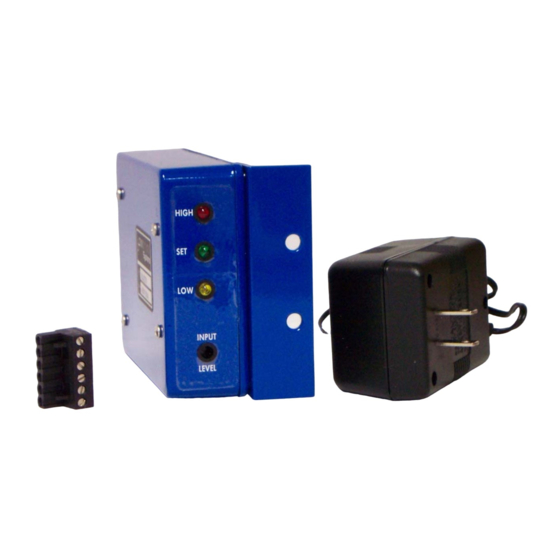
- Page 4 Connect the power cube into a suitable power strip or socket. Take the other end of the power wire and plug it into the rear of the ALM771 labeled POWER. Now you should see an LED lit on the front of the unit.
- Page 5 Do not re-adjust INPUT SET controls. Set the channel balance of the program sources in your system. The green LED lights on the two ALM771 units can be used as an indicator of channel balance. Next connect a wire from the ST position on the connector block to the ST connector on the second connector block.
Need help?
Do you have a question about the ALM771 and is the answer not in the manual?
Questions and answers