Advertisement
Quick Links
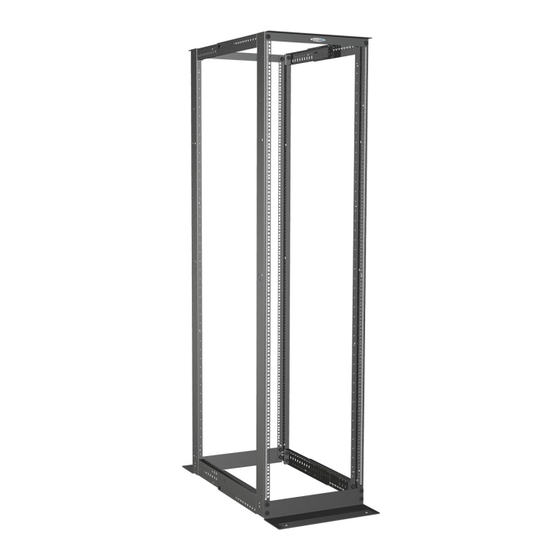
Enhanced Rack Series
6
Installation Instructions
Instructions for the following Great Lakes Racks and Accessories:
VD4PM6-2436, VD4P1224-2436, VD4PHD-2436,
6
VSBK6-8, VSBK9-14, 4PBK24-36, 4PBK12, 4PBK16,
4PBSF24-36, 4PSPV24-36, PDU2ER, PDU3ER,
VCM12-FO-ER, 4PLRBV4-8, ESF24-29, ESF16
WeRackYourWorld.com
1-866-TRY-GLCC (879-4522)
5
CMR-45U16, CMR-45U
5
4
INTERPRET DRAWING PER ASME Y14.5M-1994
DIMENSIONAL LIMITS APPLY
AFTER APPLICATION OF FINISH
DRAWING NOT TO SCALE
TOLERANCE UNLESS OTHERWISE NOTED:
ANGULAR +/- 1
.XXXX +/- .010
.XXX +/- .015
EST. WEIGHT :
.XX +/- .030
N/A
.X FOR REF. ONLY
THIRD ANGLE
UNLESS OTHERWISE SPECIFIED
PROJECTION
ALL DIMENSIONS ARE IN INCHES
4
3
NOTICE:
Use of this document is subject to
a confidentiality and nondisclosure
agreement with Great Lakes Case
& Cabinet Co., Inc. (GLCC) and may
not be reproduced, disclosed or
utilized in whole or in part without
prior written authorization from GLCC.
3
2
PART NUMBER:
Catalog
QTY PER UNIT:
MATERIAL TYPE:
MATERIAL GAUGE
FINISH:
DRAWN
CaiusD
CHECKED & APP.
2
Advertisement

Summary of Contents for Great Lakes Case & Cabinet VD4PM6-2436
- Page 1 TOLERANCE UNLESS OTHERWISE NOTED: agreement with Great Lakes Case MATERIAL GAUGE ANGULAR +/- 1 & Cabinet Co., Inc. (GLCC) and may .XXXX +/- .010 VD4PM6-2436, VD4P1224-2436, VD4PHD-2436, not be reproduced, disclosed or FINISH: .XXX +/- .015 EST. WEIGHT : .XX +/- .030...
-
Page 2: Installation
PREFACE This manual is provided to prevent service personnel from committing an act that results in the risk of fire, electric shock, or injury to persons. Only trained service personnel should receive, unpack, and assemble the racks. In addition, only trained service personnel should install equipment in enclosures. -
Page 3: What's Included
VARIABLE DEPTH FOUR POST RACK OVERVIEW VD4PM6-2436 and VD4P1224-2436 Racks are designed to securely hold 19" rack mount equipment, networking equipment, etc. Components of the Variable Depth Rack will ship in three separate boxes. Boxes will be marked with the box number and an item number. - Page 4 DETAIL D (TOP BRACKET WITH #12-24 MOU TOOLS 3/4" socket & 3/4" wrench Top Rear Detail A, see page 5 Cross Member Top Width Bracket Top Front Extension Bar When assembled, Vertical Upright a cross member and extension bar create the variable depth side rail.
- Page 5 To assemble a cross member and extension bar, determine the desired rack depth. Insert the small square tab of the rear member cross piece into the correct square hole on the extension bar. Firmly push down on the cross member so that the tab is inserted firmly into the extension bar hole.
- Page 6 (Detail B - Bottom Width Brackets) Vertical Upright Bottom Variable Depth Side Rail 1/2"-13 x 1" lg. Hex Cap Screw 1/2" Ext. Tooth Washer 1/2" Ext. Tooth Washer 1/2"-13 Hex Nut DETAIL A (TOP BRACKET-RAILS WITH M6 MOUNTING) 1/2"-13 x 1" lg. 1/2"...
- Page 7 VARIABLE DEPTH HEAVY DUTY 4 POST RACK OVERVIEW VD4PHD-2436 Racks are designed to securely hold 19” rack mount equipment, networking equipment, phone equipment, etc. All components of the VD4PHD-2436 ship in the same box. What’s Included: Component Qty. Vertical Uprights (2 left/2 right) Rack Mounting Hardware Width Brackets Rack Assembly Hardware...
- Page 8 TOOLS 3/4" socket, 3/4" wrench and (T45) torx drive Horizontal Width Bracket Variable Depth Bracket Horizontal Width Bracket Vertical Rail 3/8" sq. (M6) Mounting Detail A, see page 10 ASSEMBLY The variable depth side rails are assembled by snapping together a cross member piece and extension bar.
- Page 9 Left Variable Right Variable Depth Side Rails Depth Side Rails Top Rear Extension Bar Top Front Cross Member Bottom Front Cross Member Bottom Rear Extension Bar To assemble a cross member and extension bar, determine the desired rack depth. Insert the small square tab of the rear member cross piece into the correct square hole on the extension bar.
- Page 10 Assemble the top and bottom width brackets to uprights (place the width bracket with the GLCC label on top) using 3/8 -16 x 3/4" flat head screws. Align the uprights so that the #1 on the RMU labels is toward the bottom.
- Page 11 CMR-45U16 AND CMR-45U CABLE MANAGEMENT RACK OVERVIEW CMR Racks are designed to securely hold 19" rack mount equipment, networking equipment, phone equipment, etc. The CMR-45U16 and CMR-45U each include componenets listed below, except where noted. All componets ship in the same box. WHAT’S INCLUDED Component Qty.
- Page 12 CMR-45U16 CABLE MANAGEMENT RACK TOOLS T45 bit, socket type with ratchet preferred ASSEMBLY Install front waterfall cross-brace and horizontal width bracket A. Lay Upright Channels on edge and open sides of the channel to face each other. B. Align pem nut in Cross Brace Waterfall Edge behind the top thru holes in the Upright Channels (for 19"...
- Page 13 APPROVED #12-24 Pan Head Screw Cross-brace Waterfall 3/8-16 x 3/4" Edge lg Flat Head Screws (T45) Center Waterfall Cross-brace Bracket Waterfall Edge Cable Management “Fingers” Upright Channel #12-24 Pan Head Screw Cable Management “Fingers” 3/8-16 x 3/4" lg Flat Head Screws (T45) Upright Channel Thru Holes for...
- Page 14 CMR-45U CABLE MANAGEMENT RACK TOOLS 9/16" socket or wrench ASSEMBLY Install front cross-brace and front horizontal width bracket A. Lay Upright Channels on edge and open sides of the channel to face each other. B. Locate thru holes at the top of the channel; align Cross Brace Waterfall Edge behind the top holes (for 19"...
- Page 15 Center Waterfall Bracket #12-24 Pan Head Screw Cross Brace Waterfall Edge 3/8"-16 x 1" lg Hex Head Bolt 3/8" Ext. Tooth Lock Washer 3/8" - 16 Hex Nut Cable Ring Upright #12-24 Pan Channel Head Screw 3/8" Ext. Tooth Lock 3/8"...
- Page 16 The following parts are not effectively bonded to the protective earthing terminal: Top and Bottom Inside Extension Bars - and Top and Bottom Outside Cross Members on the VD4PM6-2436, VD4P1224-2436 and VD4PHD-2436 Racks and the Center Waterfall Bracket on the CMR-45U and CMR-45U16.
- Page 17 RELATED ACCESSORIES AND PARTS SPACER BRACKETS, VSBK6-8, VSBK9-14 Variable Spacer Bracket Kits are adjustable in one inch increments and are required when installing a vertical cable manager or baffle between two racks. Each kit contains 4 bracket assemblies. Before installation of brackets, take into consideration if a vertical cable manager will also be installed between the racks.
- Page 18 SIDE AIRFLOW BAFFLES, 4PBK24-36, 4PBK12, 4PBK16 Tools: 3/8" socket and philips head screwdriver Available baffle kits include: 4PBK24-36 84"H baffle kit for 4 Post Racks, variable depth of 24-36"; for use when racks are set from 24-36" 4PBK12 84"H baffle kit for CMR-45U, set at 12" deep 4PBK16 84"H baffle kit for CMR-45U16, set at 16.25"...
- Page 19 BAFFLE SUPPORT FRAME, 4PBSF24-36 Tools: philips head screwdriver Use the Baffle Support Frame when a baffle is needed for an end-of- row rack. Support frame is not recommended for the CMR-45U16, as the frame has a variable depth from 24-36" and the CMR is only 16". 1.
- Page 20 RACK SIDE PANEL, 4PSPV24-36 No tools required 1. The inner panel has holes along the top and bottom horizontal edges. Align the inner panel to the left side of the support frame (or rack) and insert a push button rivet in the first hole on the top and bottom, as shown in Detail A.
- Page 21 PDU BRACKETS, PDU2ER, PDU3ER Tools: philips head screwdriver 1. Choose which location to mount the PDU brackets to and use required hardware as shown in Detail A, B, or C. The height of the PDU and position of buttons on the PDU should be taken into consideration when installing the brackets.
- Page 22 12" VERTICAL CABLE MANAGER INSTALLED WITH 4 POST RACK VCM12-FO-ER Tools: 7/16" socket and wrench 1. Place the cable manger between 2 racks, racks will need spaced at 14" apart. Attach the manager to the racks (in all 4 corners), as shown in Detail A.
- Page 23 12" VERTICAL CABLE MANAGER INSTALLED WITH 2 POST RACK VCM12-FO-ER Tools: 1/4" socket and wrench 1. One EIA Mounting Bracket will be mounted at each corner of the VCM-12. Brackets are specific to the top and bottom as well as the left and right of the VCM-12.
- Page 24 LADDER RACK BRACKETS - 4PLRBV4-8 Tools: 3/8" and 7/16" socket 1. Brackets are height adjustable from 4"-8", in one inch increments. Determine the necessary height of the bracket; set the height by securing the adjustable base and radii top together. If 4" is the 4.500 R3.072 24.250...
- Page 25 EQUIPMENT SUPPORT FRAME FOR 4 POST RACKS - ESF24-29 Tools: 3/8" and 7/16" socket, philips head screwdriver The equipment support frame is designed for the variable depth 4 post racks; however, the frame is only adjustable from 24"-29", so it cannot be used in a rack that is set beyond 29"D.
- Page 26 EQUIPMENT SUPPORT FRAME FOR ESF16 CMR-45U16, ESF16 CMR-45U16 Tools: philips head screwdriver 1. Determine which RMU the support frame needs installed in; use #12-24 screws to attach frame to rack. 2. FINGER TIGHTEN all screws and then go back and tighten screws with screwdriver.
-
Page 27: Loading Equipment
SAFETY CONSIDERATIONS WARNING: Improper handling and use of the racks could result in equipment damage, serious injury, or possible death. Only trained service personnel should be used to remove the enclosure from the pallet. Also, be sure you have a sufficient number of service personnel. - Page 28 Thank you for your business! ETSI Associate Member FORM: #MS - 5.02-31, REV 3...
Need help?
Do you have a question about the VD4PM6-2436 and is the answer not in the manual?
Questions and answers