
Related Manuals for Heise PTE-2

Summary of Contents for Heise PTE-2
- Page 1 HEISE PTE-2 Operation and Maintenance Manual All specifications are subject to change without notice. All sales subject to standard terms and conditions. ©2021 Ashcroft Inc., I&M002-10225_PTE-HHC_RevB_06-03-21...
- Page 3 Congratulations on your purchase of a Heise PTE-2, one of the finest precision pressure measuring instruments available any- where. These instruments are precision devices, designed to measure, indicate pressure, temperature, DC voltage or current with an extremely high degree of accuracy and are rugged enough to provide laboratory performance in field service.
-
Page 4: Table Of Contents
TABLE OF CONTENTS (cont.) g. Switch Test ......................35 h. Percent (%) Error Function ..................37 Dual Mode Functions ...................41 Decay Leak Test ....................42 RTD Temperature Measurement ................44 k. Thermocouple Temperature Measurement ............47 Firmware Update ....................48 m. Communications Interface ...................57 USB Cable Installation ...................57 ii. - Page 5 • Provide power to devices from an internal 24Vdc loop supply (non-I.S. only) TERMS IN THIS MANUAL Terms used in this manual • HHC or Base Unit refers to the Model PTE-2 Hand held Calibrator Base Unit • Capacitive Module refers to Model HM2-1 low pressure sensor module •...
- Page 6 250 East Main Street Stratford, CT 06614-5145, USA Tel: 203-378-8281 Fax: 203-385-0402 email: heise@ashcroft.com Please be sure to include instrument model number and serial number in all correspondence to assure proper identification. Ashcroft Inc. does not recommend trouble-shooting or repairs beyond the scope of this manual.
- Page 7 • Do not operate the calibrator near explosive gas or vapor unless the calibrator is marked as approved for hazardous area service. • Never open the PTE-2. There are no field serviceable components. This will void the warranty. • When measuring pressure, be sure that the process pres- sure line is shut off and depressurized before connecting or disconnecting a pressure module.
- Page 8 ADDITIONAL WARNINGS CONT. 2 5 0 EA S T MAI N S T. S T R AT FO R D , C T 0 6 6 1 4 w w w. a s hc ro f t. c o m INTRINSICALLY SAFE/SÈCURITÈ...
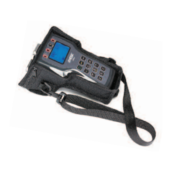
- Page 9 SECTION 2.0 INTRODUCTION The PTE-2 is a simple, yet sophisticated, high accuracy, battery or USB powered, handheld calibrator device. Used together with interchangeable pressure and temperature modules, this device measures, displays and can record pres- sure, temperature, DC voltage or milliamp current. Up to three measurements can be simultaneously displayed.
- Page 10 SECTION 3.0 PRODUCT SPECIFICATIONS BASE UNIT PHYSICAL SPECIFICATION Dimensions 8.7” L X 5.1” W X 3.8” H Weight 2.4 pounds (includes two modules installed) Case Material High Impact PC-ABS with rubberized sections Sensor Module Capacity 2, hot swappable, modules are fully recognized automatically Display 1.5”...
- Page 11 SECTION 3.0 PRODUCT SPECIFICATIONS CONT. Activated Activated Feature or Function from Key Pad from Menu On/Off Backlight Menu Flip Screen Navigation Keys (4) Port Select Zero mA / V Damping Tare Capability Min / Max Tracking Data-Logging w/auto start/auto stop Field Calibration (Base Unit and pressure modules) Passcode Lock...
- Page 12 SECTION 4 BASE UNIT OVERVIEW The base unit functions as a host for the Quick-Select pres- sure and temperature modules. The base unit includes two bays for installation of pressure or temperature modules, an LCD graphic display with back light, a key pad, a USB micro B receptacle for communication with a PC, an SD memory card slot and banana jack connections for DC voltage supply and signal monitoring.
-
Page 13: • Percent Error Function
SECTION 4 BASE UNIT OVERVIEW CONT. The operator can program several parameters in the calibrator which are further detailed in this manual. Programmable parameters include: • Date and time • Owner name • Auto off time • Port selection • Select Voltage (v) or current (mA) monitoring •... - Page 14 SECTION 6 QUICK-SELECT MODULE Quick-Select modules when installed in the base unit are referred to as Channel 1 and Channel 2. Channel 1 is always OVERVIEW CONT. the module on the left side of the calibrator when it is held upright with modules at the top of the calibrator and the LCD display facing the operator.
- Page 15 SECTION 6 QUICK-SELECT MODULE HM2-TC1 temperature modules read types J, K, T, E, R, S, B and N thermocouples and display the measurement in units of OVERVIEW CONT. degrees Fahrenheit, Celsius, Kelvin, Rankin or millivolts. System protection modules HM2-XS are used to protect unused sensor bays in the base unit from moisture or other contamination ingress as well as EMI/RFI interference.
- Page 16 SECTION 7 UNPACKING Prior to removing the HHC from the packaging material, inspect all cartons for shipping damage. Document any damage evident in the event that a damage claim must be made against the shipper. After inspection, remove the base unit, module(s), manual and any accessories purchased from the packaging material.
- Page 17 SECTION 11 MODULE INSTALLATION 1. Hold the base unit, in one hand, with the keypad side DOWN. 2. Holding the Quick-Select module to be installed in the other hand, align the module with the locking tab up, with the module bay on the base unit. 3.
- Page 18 SECTION 12 STARTUP BASIC FUNCTION CONT. number, range and calibration data for each module will be briefly displayed before booting up in Measurement Mode. -0.17 -0.004 inH20 The HHC is now ready for basic pressure or temperature measurement. Pressure readings from installed modules will be displayed in the engineering unit in which the module was originally cali- brated.
- Page 19 SECTION 13 KEY FUNCTION OVERVIEW The most common functions are accessible by dedicated keys on the keypad. More complex and less often used functions and programmable features are accessible through an easy- to-navigate MENU system. A number of the keys have differ- ent functions depending in which mode the HHC is operating.
- Page 20 SECTION 14 a. ESC FUNCTION During any programming operation pressing the ESC key will cause the HHC to exit any special display mode or, step back one programming level if in Programming Mode. PORT SELECT function is used in several programming appli- SECTION 14 b.
- Page 21 SECTION 14 f. DAMPING FUNCTION The Damping Function stabilizes a measured pressure signal. When damping is activated, the value displayed, saved to a Datalog or transmitted to a journal (eg. To HyperTerminal) is a filtered value. The filtering is programmable to 16 incremental levels, allowing the damping function to be tailored to the spe- cific requirements of most any application.
- Page 22 SECTION 14 g. MANUAL DATALOG FUNCTION To close a Datalog and prepare the HHC to begin a new Datalog CONT. press the ESC key. The next press of the DATA STORE key will begin a new Datalog and will continue to record data in the new log with every subsequent press of the key.
- Page 23 SECTION 14 h. TARE FUNCTION CONT. –0.000 -0.24 inH20 Tare 0.000 Exit Tare Mode Press TARE key Press PORT SELECT key repeatedly to select Channel 1, Channel 2, or both active pressure modules Press ENTER Selected modules are now in Measurement Mode without a tare value.
- Page 24 SECTION 14 i. mA/V FUNCTION The HHC has the capability to monitor either DC milliamp current 0-22 mA or DC voltage 0-33 Vdc. Use of this feature requires connection to the voltage or current source via the 4mm “Banana Jacks” located above the units LCD. Note that this calibrator can monitor only one parameter, either voltage or current, at a time.
- Page 25 0-22mA In 0-22mA In 24Vdc Out 24Vdc Out 0-33Vdc In 0-33Vdc In SECTION 14 j. WIRING DIAGRAMS CONT. SWITCH HOOKUP USING INTERNAL SUPPLY SWITCH NORMALLY OPEN EXTERNAL 24 VOLT DC RESISTOR* – 0-22mA In 24Vdc Out 0-33Vdc In *Resistor should be sized to allow current as follows: 2 mA <...
- Page 26 SECTION 14 k. 24 VDC POWER SUPPLY ENABLE AND DISABLE 15.34 0.10 inH2O 0.000 Loop supply overloaded Remove the excessive load from the circuit and attempt to activate the 24v loop power supply via the MENU as described above. If the excessive load is not removed from the circuit upon acti- vation, the loop supply will be disabled and the following warn- ing message will be displayed 15.29...
- Page 27 SECTION 14 l. MIN/MAX FUNCTION CONT. –0.010 Max: 6.21 Min: –11.20 inH20 0.000 To clear active Min/Max measurements press the ZERO key. To exit Min/Max mode completely press the ESC key. Note: Datalogs recorded while in Min/Max Mode will record the real time pressure measurements at the time of writing to the Datalog, not the min/max values.
- Page 28 SECTION 15 a. MENU MODE GENERAL KEY and are also used to scroll through programmable parameters FUNCTIONS CONT. such as alpha numeric characters when programming names. LEFT and RIGHT ARROW Keys DAMP/LEFT ARROW and TARE/RIGHT ARROW keys are dual function keys which are used in MENU Mode to move the cursor to the right or left.
- Page 29 SECTION 15 b. ii. Programming Owner Name Programming Owner Name (15 Characters max) Press MENU key Press DOWN or UP ARROW key to highlight “Setup…” Press ENTER Press DOWN or UP ARROW key to highlight “System” Press ENTER Press DOWN or UP ARROW key to highlight “Owner…” Press ENTER Owner Password screen appears.
- Page 30 SECTION 15 b. iii Program Auto Off Timers Cont. Press ENTER Use DOWN or UP ARROW to highlight “Auto off timer…” Press ENTER Use DOWN or UP ARROW to highlight “Power off”… Use DOWN or UP ARROW to highlight “Backlight off”… Auto Off Modes Power Off…...
- Page 31 SECTION 15 d. O TEMPERATURE CONVERSION If the user selects an engineering unit which references water SELECTION column pressure, they can select a water temperature to factor into the conversion. The pressure generated by a column of water will vary with the temperature of the water. As there are industry standard temperatures used as conversion factors when calibrating pressure measurement devices in terms of the height of a column of water, the HHC uses three(3) conver-...
- Page 32 SECTION 15 e. PROGRAMMING USER DEFINED Press left and RIGHT ARROWs to position cursor beneath UNIT OF MEASURE CONT. desired character Press UP and DOWN ARROWs to increment alpha and numeric characters When the Unit name is correct press ENTER HHC will return to “User Units”...
- Page 33 SECTION 15 f. i. Program Channel Tag Names Program Channel Tag Names (up to 7 characters) The default channel names, Channel 1, Channel 2 and Ext can be re-programmed by the user. Press MENU key Use DOWN or UP ARROW to highlight Datalog… Press ENTER Use DOWN or UP ARROW to highlight Set channel tags……...
- Page 34 SECTION 15 f. ii. Program Auto Datalog Time Cont. Set log interval Desired: 00001.0 sec Actual: 00001.2 sec Enter to accept Esc to cancel “^ “Beneath a digit indicates which character in the time interval name is being configured. Press UP or DOWN ARROW to scroll through numeric values Use left or RIGHT ARROW to move cursor to next desired position.
- Page 35 SECTION 15 f. iv. Initate Manual Datalog Cont. Use DOWN or UP ARROW to highlight “Manual/Auto…” Press ENTER Use DOWN or UP ARROW to highlight Manual or Auto, select “Manual…” Press ENTER Display will return to Measurement Mode. Press DATA STORE to begin a new manual Datalog. Display will briefly show “Data point Taken”...
- Page 36 SECTION 15 f. v. Review Datalogs Cont. Press ESC to go back to “Select Datalog” screen and choose another log to review. The HHC contains a slot for a standard SD memory card. SECTION 15 f. vi. Export Datalogs to SD Card When a card is installed Datalogs can be exported to the card in .CSV (Comma Separated Values) files which are able to be read by Microsoft Excel or other spread sheet software.
- Page 37 SECTION 15 f. vii Clear Internal Memory Storage Delete all logs? Cont. Are you sure you want to clear all internal storage? Use DOWN or UP ARROW to highlight Yes or No Press ENTER Selecting “no” will return to the Datalog MENU Selecting “yes”...
- Page 38 SECTION 15 g. SWITCH TESTING FUNCTION CONT. Use DOWN or UP ARROW to highlight “Measurement Chan- nel…” Press ENTER Use DOWN or UP ARROW to highlight “CH1” (Channel 1 module) or “CH2” (Channel 2 module)… Press ENTER HHC will go back to Switch Testing MENU Use DOWN or UP ARROW to highlight “Signal Type…”...
- Page 39 SECTION 15 h. PERCENT (%) ERROR FUNCTION The Percent Error Function allows the user to display the output from a device under test in terms of percent error of the full scale range of that device. This function applies to the calibration of both temperature and pressure devices.
- Page 40 SECTION 15 h. PERCENT (%) ERROR FUNCTION Output refers to any output signal from the device under test. CONT. Output channel refers to the channel on which the device under test is sending its output signal. For example a pressure transducer with 0-10 VDC output would be connected to the HHC’s External input, referring to the banana jacks labeled COM and 0-33 Vdc In.
- Page 41 SECTION 15 h. PERCENT (%) ERROR FUNCTION Input range CONT. 4-20 Custom Use DOWN or UP ARROW to highlight 4-20, 0-X, 1-X or Custom Note: If a range ending in “–X” or “Custom” is selected the operator can program the numeric value for the variable as follows If a custom range is required: Use DOWN or UP ARROW to highlight “Custom”…...
- Page 42 SECTION 15 h. PERCENT (%) ERROR FUNCTION When desired FS input value is displayed on screen for example CONT. 00110.00000 Press ENTER to accept HHC will go back to Percent Error MENU and advance to the next programmable parameter. Use DOWN or UP ARROW to highlight “Output channel…” Press ENTER Use DOWN or UP ARROW to highlight “CH1”...
- Page 43 SECTION 15 h. PERCENT (%) ERROR FUNCTION Output FS CONT. 00006.00000 Enter to accept Esc to cancel Press left and RIGHT ARROWs to position cursor beneath desired numeric character Press UP and DOWN ARROWs to scroll numeric values. When desired numeric value is displayed in proper decimal position Press left or RIGHT ARROW to move cursor beneath the next digit to be programmed...
- Page 44 SECTION 15 i. DUAL MODE FUNCTION CONT. Dual sensor differential measurements will have similar accu- racy specifications. To access Dual Module Functions: Press MENU key Use DOWN or UP ARROW to highlight “Modes…” Press ENTER Use DOWN or UP ARROW to highlight “Dual module func- tions…”...
-
Page 45: Dual Mode Functions
SECTION 15 i. DECAY LEAK TEST CONT. Modes Dual mode functions... Percent error... Switch testing... Decay leak test Press ENTER Press DOWN or UP arrow to highlight desired leak test time period or “Custom” If 30 or 60 seconds is selected, press ENTER to immediately begin test. -
Page 46: Rtd Temperature Measurement
Switchcraft TA4M type connector and requires an RTD with the appropriate mating connector. The connector is available through the supplier of your choice. Setting up the PTE-2 for an RTD Temperature Measurement Insert the appropriate XXX-RT Quick-Select RTD Interface Module. - Page 47 SECTION 15 j. RTD TEMPERATURE To select RTD probe characteristics MEASUREMENT CONT. Install an RTD Quick-Select Module and Probe in the HHC Base Unit. Press MENU key Use DOWN or UP ARROW to highlight “Setup…” Press ENTER Use DOWN or UP ARROW to highlight “Module…” Press ENTER Use DOWN or UP ARROW to highlight “RTD…”...
- Page 48 SECTION 15 j. RTD TEMPERATURE Note: The maximum resolution that the combination of the HHC MEASUREMENT CONT. base unit and the RTD interface module and probe can support can be determined as follows: The resolution of the RTD module is 0.001% of the full scale resistance of the reference resistor used in the module.
-
Page 49: Thermocouple Temperature Measurement
TC Junction Type Thermocouple Type: J Fe-Cu/Ni Note; By selecting the thermocouple type the PTE-2 will access the factory programmed coefficients in the module which will allow the PTE-2 to display in a unit of temperature Return to TC Module screen Use DOWN or UP ARROW to highlight “Auto/manual ref…”... -
Page 50: Firmware Update
SECTION 15 k. THERMOCOUPLE TEMPERATURE If Manual was selected continue below MEASUREMENT CONT. TC Manual Ref 00000.00 Enter to accept Esc to cancel Press left and RIGHT ARROWs to position cursor beneath desired numeric character. Press UP and DOWN ARROWs to scroll numeric values. When desired numeric value is displayed in proper decimal position, press LEFT or RIGHT ARROW to move cursor beneath the next digit to be programmed. - Page 51 SECTION 15 l. FIRMWARE UPDATE CONT. Certified.zip On the supplied memory stick: D:\HHC_Utilities\FTDI_Driver\CDM 2.08.30 WHL Certified.zip 2) Install the HCC Firmware Updater on the Host PC: The “HHC Firmware Updater” is a Windows software utility that allows you to transfer an HHC firmware image, in the form of a “.cyacd”...
- Page 52 SECTION 15 l. FIRMWARE UPDATE CONT.
- Page 53 SECTION 15 l. FIRMWARE UPDATE CONT.
- Page 54 SECTION 15 l. FIRMWARE UPDATE CONT. 3) Download the HHC Firmware Image to the Host PC: HHC Firmware images have the filename extension “.cyacd”. Example: “pte2 v_050-083.cyacd” Simply copy this file onto your local hard drive, making a note of its path so you can find it. 4) Connect the HHC to the Host PC: Using the supplied USB cable, connect the HHC to an open USB port on your Host PC.
- Page 55 SECTION 15 l. FIRMWARE UPDATE CONT. Select the appropriate COM port. TIP: When you pull DOWN “Select Com Port” it scans your computer and presents a list of available COM Ports. If you do this before and after connecting the USB cable to the HCC, you should see an extra com port with the HHC connected.
- Page 56 SECTION 15 l. FIRMWARE UPDATE CONT. Both the “Com port status” and the “Device Status” should indicate “Connected”. NOTE: If the “Com Port Status” is “Connected” and the “Device Status” is “Disconnected” you most likely have the wrong COM port or the device is not in the “Firmware Update” mode. If unsure of the correct COM port number disconnect the USB cable from the PC then reconnect to have the PC display a message stating the new COM port number.
- Page 57 SECTION 15 l. FIRMWARE UPDATE CONT. Note: The File Transfer can take up to 15 Minutes.
- Page 58 SECTION 15 l. FIRMWARE UPDATE CONT. When the “Transfer Successful” message is displayed the pro- cess has completed. You can verify the update was successful by powering on the HHC base unit and noting the new firmware revision number displayed during boot up and in the “about this HHC…”...
-
Page 59: Communications Interface
SECTION 15 m. COMMUNICATIONS INTERFACE The HHC can be connected to a PC running Windows XP or Windows 7, 8 or 10 via the USB port. Windows will recognize the HHC as a Communications Port. The HHC has three communication protocol modes: Inquiry/Journal mode: These communications modes are included in standard HHC models. -
Page 60: Driver Installation
SECTION 15 m. i. USB Cable Installation Cont. IMPORTANT NOTE for INTRINSICALLY SAFE APPROVED VERSIONS OF THE Hand Held Calibrator 1. When access port is open, the device is not operating in an Intrinsically Safe mode. As such it is not possible to use the HHC in a hazardous area whenever the USB port is exposed or if the port access door is not secured with Philip’s head screw. - Page 61 SECTION 15 m. ii. Driver Installation Cont. If the following dialog box appears, click “Browse my Computer” The dialog below will appear. Click “Browse and navigate to the drive with the memory stick, then click Next. Windows will install the driver. Once complete an HHC will enu- merate as a Communications Port on this computer.
-
Page 62: Terminal Setup
SECTION 15 m. ii. Driver Installation Cont. The HHC will appear as a Communications Port on a Windows PC. It will be assigned the port number of the first available port on the PC. To determine which port number has been assigned look in the Windows Device Manager. -
Page 63: Inquiry Mode
SECTION 15 m. iv Inquiry Mode Set up Inquiry Mode Inquiry mode is similar to manual datalogging where a data point will be sent to the PC based on a user defined character or the Enter key being pressed from the PC keyboard. Press MENU key Use DOWN or UP ARROW to highlight “Modes…... -
Page 64: Journal Mode
SECTION 15 m. v. Journal Mode Set up Journal Mode Journal mode is similar to Automatic Datalogging mode where the operator can set a timed interval between data points being communicated to the PC. In Journal Mode the HHC will output the data string at a time interval set by the user. - Page 65 SECTION 15 n. CALIBRATE BASE UNIT CONT. Obtaining “As found” and “As Left” data procedure consists of applying precision voltage and current signals to the proper terminations and reading the values displayed on the HHC display. Base unit recalibration is a firmware based, menu driven pro- cedure that provides prompts on the HHC display directing the operator to apply precision voltage and current signals to designated terminals.
- Page 66 SECTION 15 n. CALIBRATE BASE UNIT CONT. Documenting Calibration Data Procedure NOTE: The input jacks for the 10 and 30 volt inputs are the same input jacks, the accuracy statement for 10 volts is for values between 0 and 10 volts DC, the accuracy statement for 30 volts DC is for values above 10 volts to 30 volts DC VOLTAGE JACK INPUT, 0-10 volts 1.
- Page 67 SECTION 15 n. CALIBRATE BASE UNIT CONT. 12. When test is complete, set voltage standard to 0.00 volts and disconnect the leads from the HHC. CURRENT JACK INPUT 1. Connect the negative lead of the current source to the black ringed “COM” input jack 2.
- Page 68 SECTION 15 n. CALIBRATE BASE UNIT CONT. 7. Connect the positive lead of the voltage source to the red terminal on the Calibration Module 8. Power on the HHC using either USB or battery power and allow it warm up to its specified accuracy (5 minutes) 9.
- Page 69 SECTION 15 n. CALIBRATE BASE UNIT CONT. c. Press ENTER d. Press DOWN or UP ARROW key to highlight “Calibrate” e. Press ENTER Cal Password screen appears. Enter Calibration Pass- word Cal Password 00000 Enter to accept Esc to cancel f.
- Page 70 SECTION 15 n. CALIBRATE BASE UNIT CONT. 16. The HHC Base Unit will prompt the operator to apply pre- cision voltage values to specific terminals, data collection will take a few seconds then the HHC will prompt the oper- ator to move to the next step in the following sequence : a.
-
Page 71: Pressure Module Calibration
SECTION 15 o. PRESSURE MODULE CALIBRATION Pressure modules can be recalibrated and certified in the field. The procedure allows for the acquisition of “as found” and “as left” data, and recalibration of the pressure module. Field calibration typically consists of three steps. Step one is to document the “as found”... - Page 72 SECTION 15 o. PRESSURE MODULE CALIBRATION CONT. Cal Password 00000 Enter to accept Esc to cancel Press left and RIGHT ARROWs to position cursor beneath desired character g. Press UP and DOWN ARROWs to increment numeric characters h. When the password is correct press ENTER “Calibrate”...
- Page 73 SECTION 15 o. PRESSURE MODULE CALIBRATION the target cardinal pressure value, actual target pressure CONT. can be edited within the Min and Max limits. This value is the pressure reading which is displayed on the external pressure calibration standard. The following is defined as “Zero Pressure” for various pressure types: Absolute Absolute Zero (using vacuum pump)
- Page 74 SECTION 15 o. PRESSURE MODULE CALIBRATION The first linearization point target pressure and min and CONT. max allowable limits in default engineering units will be displayed. Using the pressure standard, apply the target pressure to the module. If the pressure standard does not achieve exactly the target cardinal pressure value, actual target pressure can be edited within the Min and Max limits.
- Page 75 SECTION 16 a. APPENDIX A – ENGINEERING UNIT CONVERSION FACTORS ...
-
Page 76: Trouble Shooting And Error Codes
USB device. USB PORT Plug the PTE-2 into the USB port of a PC. If the unit fails to power up either the USB port is faulty, the cable is bad, or the HHC has failed. - Page 77 HHC. The SD card may be faulty, change the SD card In order to ensure compatibility with the majority of manufacturers, the PTE-2 was developed using a number of different types of SD cards try using one of these recommended SD cards. (See section 16g) Refer to the manual and repeat steps required to export data.
- Page 78 _ Note that the COM connection is not required here as they share this connection internally to the PTE-2. Note: The power supply of a non-intrinsically safe base unit exhibits a leakage voltage of approximately 1 volt in the off condition.
- Page 79 SECTION 16 b. TROUBLE SHOOTING CONT. tab is fully seated in its mating hole at the bottom of the base unit. Turn the base unit back on, pressure should be displayed after the units booting process. If pressure is not displayed, try another pressure module if available.
- Page 80 Hardware Warnings • CH1 F.S. INVALID/ CH2 F.S. INVALID: Danger, the PTE-2 may not display the full scale psi when applied (A legacy PTE-1 module with invalid output at full scale) Contact Customer Service • CH1 Low Span / CH2 Low Span...
-
Page 81: Iso Commands
(hex) in BCC = printable (hex) xor’d <cmd> HHC command BCC = byte[2] ^ byte[3] ^ byte[5] ASCII code PTE-2 Response is the same format proceeded by an ACK, a NACK is sent alone if the command is not understood. - Page 82 SECTION 16 c. ISO COMMANDS PTE-2 ISO1745 Commands Description Command Code Returns the datalog Get datalog status information as an ASCII string Go to the top of the next datalog Returns the data for the present record in Get datalog record...
- Page 83 SECTION 16 d. APPENDIX D APPENDIX D SWITCHCRAFT TINI QG (TA4F) FUNCTION 4W– 2W– 2 WIRE RTD TA4F 3 WIRE RTD TA4F 4 WIRE RTD TA4F...
-
Page 84: System Accuracy With Thermocouple Interface
SECTION 16 e. SYSTEM ACCURACY WITH THERMOCOUPLE INTERFACE TABLE I System Accuracy (reading in temperature units): Includes the HHC base unit and XXX interface module. (Does not include inaccuracy of the thermocouple device. Consult thermocouple manufacturer or ISA MC96.1 for thermocouple accuracy specifications. Typical inaccuracies range from ±1 to ±2.2°C.) Max. - Page 85 WARRANTY AND LIMITATION OF LIABILITY WARRANTY INFORMATION A. Seller warrants that its products and parts, when shipped, and its work (including installation, construction and start-up), when performed, will meet all applicable specifications and other specific product and work requirements (including those of per- formance), if any, of this agreement, will be of good quality and will be free from defects in material and workmanship.
- Page 86 NOTES...
- Page 88 Tel: (203) 378-8281 Fax: (203) 385-0402 (Domestic) Fax: (203) 385-0357 (International) email: info@heise.com www.heise.com Visit our web site at www.heise.com All specifications are subject to change without notice. All sales subject to standard terms and conditions. ©2021 Ashcroft Inc., I&M002-10225_PTE-HHC_RevB_06-03-21...
Need help?
Do you have a question about the PTE-2 and is the answer not in the manual?
Questions and answers