Table of Contents
Advertisement
Quick Links
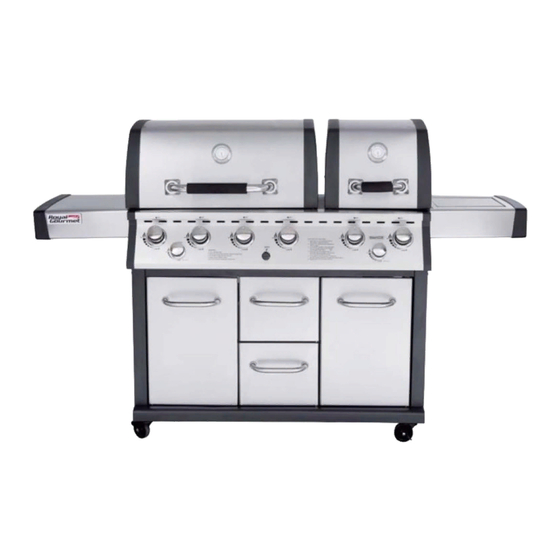
Mirage Two Split Lid 6-Burner Gas Grill
with Infrared Burner MG6001-R
FOR YOUR SAFETY!
Use outdoors only! Do not use it in a building,garage or any other enclosed area.
Read the instructions before assembling and using the appliance.
DO NOT use the grill unless it is completely assembled and all the parts are securely fastened.
This grill will become very hot, do not move it during operation.Keep children and pets away.
CONTACT US FIRST!
This grill has been made to high quality standards. If you have any questions nor
addressed in this manual, or if you need parts, please call our customer service department,
or send an email to service
Learn more at:
OWNER'S MANUAL
@
royalgourmetusa.com.
.
Customer Service
1-800-618-6798
Advertisement
Table of Contents

Subscribe to Our Youtube Channel
Related Manuals for ROYAL GOURMET MG6001-R

Summary of Contents for ROYAL GOURMET MG6001-R
- Page 1 Customer Service 1-800-618-6798 Mirage Two Split Lid 6-Burner Gas Grill with Infrared Burner MG6001-R OWNER’S MANUAL FOR YOUR SAFETY! Use outdoors only! Do not use it in a building,garage or any other enclosed area. Read the instructions before assembling and using the appliance.
-
Page 2: Table Of Contents
TABLE OF CONTENTS For Your Safety Parts & Hardware List Assembly Instructions General Information and Instructions Operating Instructions Cleaning Instructions Troubleshooting Guide Frequently asked Questions Customer Service... -
Page 3: For Your Safety
WARNING FOR YOUR SAFETY 1. DO NOT store or use gasoline or any other flammable vapours or liquids within 8m(25’) of the grill. 2.When cooking with oil/grease, do not allow the oil/grease to exceed 177 Do not store extra cooking oil in the vicinity of the grill. 3.A liquid propane (LP) tank (cylinder) not connected for use should be stored a minimum of 3m(10’) away from this or any appliance. - Page 4 WARNING: 1.This grill is for outdoor use only, and should not be used in building, garage or any other enclose area. 2.The use of alcohol, prescription or non-prescription drugs may impair the operator’s ability to properly assemble or safely operate the grill. 3.
-
Page 5: Parts & Hardware List
Parts and Hardwares List 24pcs... - Page 6 PREPARATION Before beginning assembly, make sure all parts are present. Compare parts with package contents list and diagram above. If any part is missing or damaged, do not attempt to assemble the product. Contact customer service for replacement parts. Estimated assembly time: 50minutes Tools required for assembly: Phillips Screwdriver (not included) and Wrench (not included) Note: Theright and left sides of the grill are designated as if you are facing the front of the grill.
-
Page 7: Assembly Instructions
ASSEMBLY INSTRUCTIONS Step 1 Step 2 Assemble side shelf right (3) and side shelf left (4) Assemble the casters (1) to bottom shelf (2) with 16 bolts (A). to bottom shelf with 8 bolts (B). Step 4 Step 3 Assemble rear shelf right (6) to right side shelf Assemble the middle shelf (5) to bottom shelf and middle shelf with 4 bolts (A). - Page 8 ASSEMBLY INSTRUCTIONS Step 5 Step 6 Assemble the middle panel (8) to bottom shelf Assemble the rear shelf left to left side shelf, with 3 bolts (B). middle shelf and bottom shelf with 4 bolts (A) and 2 bolts (B). Step 7 Step 8 Fasten the middle panel to rear shelf with 3 bolts (A).
- Page 9 ASSEMBLY INSTRUCTIONS Step 9 Step 10 Fasten the connect panel to rear shelf Fasten the connect panel to middle panel with 2 bolts (A). with 2 bolts (A). Step 12 Step 11 Fasten the middle brace to front beam Assemble the middle brace (12) to middle shelf with 5 bolts (A).
- Page 10 ASSEMBLY INSTRUCTIONS Step 13 Step 14 Assemble the door handles (15), handle bases (16) Assemble the magnet (E) to shown position of to left & right doors with 4 bolts (B). bottom shelf with 2 bolts (G). Screw 2 (H) underneath the doors. Step 15 Step 16 Assemble the doors: connect to bottom shelf and...
- Page 11 ASSEMBLY INSTRUCTIONS Step 17 Step 18 Place the grease cups (19) onto the bases. Assemble the grease cup bases (18) to right side shelf, and middle brace, fasten them underneath firebox brace and middle brace with 6 bolts (A). Step 19 Step 20 Place the grease trays (20) , (21) onto the firebox braces Assemble the thermal baffle (22) underneath the...
- Page 12 ASSEMBLY INSTRUCTIONS Step 21 Step 22 Align and hang the side burner shelf (24) onto the Place the firebox (23) onto the braces, halfway bolts (I), and secure them. fasten it with 4 bolts (A). Fasten it with another 2 bolts (I) as shown. Screw 4 bolts (I) halfway to both upper sides of firebox, for assembling side table/burner.
- Page 13 ASSEMBLY INSTRUCTIONS Step 25 Step 26 Assemble the burner (26) underneath the Make the tube terminal insert to the side side table shelf, secure it by 1 clip (J) as shown. burner brace, secure it with 1 nut (L). Step 27 Step 28 Insert the ignition line to the electrode hole as shown.
- Page 14 ASSEMBLY INSTRUCTIONS Step 29 Step 30 Assemble the rear burner (28) to the firebox Assemble the rear burner ignitor (29) to firebox with 2 bolts (G). with 1 bolt (G). Step 32 Step 31 Connect the tube terminal to the rear burner, Make the tube insert through the rear board (30), secure it with 1 nut (L).
- Page 15 ASSEMBLY INSTRUCTIONS Step 33 Step 34 Insert the ignition line to the electrode hole Assemble the rear burner board (31) to firebox with 5 bolts (G). of rear burner ignitor as shown. Please note, fasten the bolts inside the firebox. Step 35 Step 36 Place the cooking grates (33) into the firebox.
- Page 16 ASSEMBLY INSTRUCTIONS Step 37 Step 38 Assemble the thermometer (36) to the lid. Place the warming racks (34) , (35) to the firebox. Put the AA battrey (C) into the ignitor. Step 39 Step 40 Insert the extension wire (37) to the left door.
-
Page 17: General Information And Instructions
General Information and Instructions Your new Griddle and Grill has been designed and manufactured to high quality standards. It will provide you with many years of enjoyment with a minimal amount of maintenance. Please keep in mind the following FOR YOUR SAFETY. OPERATION 1. - Page 18 CYLINDER SPECIFICATIONS: When purchasing or exchanging a tank for your gas grill, it must be constructed and marked in accordance with the specifications for LP gas cylinders of the National Standard of , CAN/CSA - B339 Cylinders, Spheres and Tubes for Transportation of Dangerous Goods, be equipped with a listed over-filling prevention device (OPD), and be equipped with a cylinder connection device compatible with the connection for outdoor cooking appliances.
- Page 19 LP CYLINDER LEAK TEST A leak test should be done each time a propane tank is refilled or exchanged. Do not smoke or use any type of flammable material in the area during this leak test. Do not use an open flame to check for leaks. 1.
- Page 20 The regular must enter the cylinder valve in a straight line. Centre the regular nipple into the cylinder valve. GCC 1 Type 1 Connector Always keep this gas cylinder in the upright position all times. WARNING 1. Do not connect this grill to any unregulated sources of propane. 2.
- Page 21 FOR YOUR SAFETY 1. The minimum distances around the barbecue that must be kept free of combustible materials, including the walls of buildings or building features are: distance from sides – 90 cm (36") and distance from back – 90 cm (36"). 2.
-
Page 22: Operating Instructions
OPERATING INSTRUCTIONS Always visually inspect your grill before lighting. Replace any hoses that are frayed or cracked. Look for anything could block spaces for ventilation and remove it or move the barbecue. After lighting, check the flame pattern to ensure you have even heat distribution for each burner. If burners won’t light, or if the flame pattern is uneven, see the Troubleshooting section. -
Page 23: Cleaning Instructions
CLEANING INSTRUCTIONS WARNING 1. Do not clean any part of your barbecue grill in a self-cleaning oven. 2. Do not use oven cleaners, abrasive kitchen cleaners, cleaners that contain citrus products, or mineral spirits. 3. Do not use any type of steel or brass bristled brush. 4. - Page 24 CLEANING THE BURNERS 1. Ensure the gas is turned off at the propane tank. 2. Remove the cooking grates, flame tamer, and grease tray. 3. Remove the cotter pins located underneath the back end of each burner. 4. Lift each burner up and out. 5.
-
Page 25: Troubleshooting Guide
Troubleshooting Guide BURNER WILL NOT LIGHT 1.) Gas supply is turned off. Turn on gas at propane tank. 2.) Out of propane. Fill or replace the propane tank. 3.) Regulator is not properly seated into the tank valve. Remove and reattach. Hand tighten only. 4.) Crimped fuel supply hose that needs to be straightened. -
Page 26: Frequently Asked Questions
One year. Customer Service Thanks for purchasing this Royal Gourmet gas grill. We are here to help you maximize your enjoyment and appreciation of your new grill. Please don't hesitate to contact us should you have any questions regarding assembly, performance,warranty, or accessories. We will be happy to order any replacement parts needed.
Need help?
Do you have a question about the MG6001-R and is the answer not in the manual?
Questions and answers