
Summary of Contents for Cutler-Hammer ATVISPE32000XSU
- Page 1 Cutler-Hammer I.B. ATS-SD02 Instructions for Cutler-Hammer Drawout Transfer Switch and Bypass Isolation Switch Effective 5/98 Replaces I.B. ATS-SDO1 dated October, 1996...
- Page 3 All possible contingencies which may arise during installation, operation or maintenance, and all details and variations of this equipment do not purport to be covered by these instructions. If further information is desired by purchaser regarding his particular installation, operation or maintenance of particular equipment, contact a Cutler-Hammer representative. Effective 5/98...
-
Page 4: Table Of Contents
I.B. ATS-SD02 Page iv TABLE OF CONTENTS PAGE SECTION 1: INTRODUCTION Preliminary Comments and Safety Precautions....................1 1.1.1 Warranty and Liability Information ......................1 1.1.2 Safety Precautions ..........................1 General Information.............................1 1.2.1 Transfer Switch Types..........................2 1.2.2 Design Configuration ..........................2 Transfer Switch Catalog Number Identification ....................4 SECTION 2: RECEIVING, HANDLING AND STORAGE Receiving................................6 Handling ................................6... - Page 5 I.B. ATS-SD02 Page v PAGE SECTION 6: DRAWOUT MECHANISM Drawout Interlock ..............................23 Switch Position ..............................23 Rotation on the Drawout............................23 Operational Check for Drawout Mechanism......................24 SECTION 7: OPERATION OF BYPASS ISOLATION TRANSFER SWITCH Operator Panel ..............................25 Automatic Operation............................25 Bypassing the Transfer Switch..........................26 7.3.1 Normal to Normal Bypass ........................26 7.3.2...
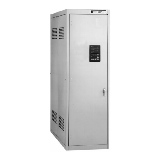
- Page 6 I.B. ATS-SD02 Page vi LIST OF FIGURES Figure Title Page Typical Load Transfer Switch (circuit breaker type) Schematic..............2 Typical Bypass Isolation Switch.........................3 Typical Bypass Isolation Switch Schematic....................3 Typical Drawout Transfer Switch with Deadfront Attached................4 Typical Power Panel ..........................7 Insulated Case Circuit Breaker ........................7 Side View and Rear View of Power Panel....................8 Drawout Mechanism ..........................9 Voltage Selection Panel ..........................9...
-
Page 7: Section 1: Introduction
In no mal and emergency power sources and supplies the event will Cutler-Hammer be responsible to the purchas- load with power from one of these two sources. In the er or user in contract, in tort (including negligence), strict... -
Page 8: Transfer Switch Types
(Sections 5 and 7 respectively). 1.2.2 DESIGN CONFIGURATION The Cutler-Hammer transfer switch is a rugged, compact design utilizing insulated case switches or insulated case circuit breakers to transfer essential loads from one power source to another (Figures 1-2 and 1-4). -
Page 9: Typical Bypass Isolation Switch
4000 3000 4000 4000 5000 Tested in accordance with UL1008. Cutler-Hammer Drawout SPB Transfer Switch will coordinate with a power circuit breaker short time rating. Contact factory for details 4000A rated switches not available in bypass isolation versions. Effective 5/98... -
Page 10: Transfer Switch Catalog Number Identification
I.B. ATS-SD02 Page 4 The switching devices are in a compact vertical arrange- significant amount of relevant information that pertains ment. The logic can be easily disconnected from the to a particular piece of equipment. The catalog number switching device without disturbing critical connections. identification table (Table 1.2) provides the required The enclosure is free standing, and, by using the spe- interpretation information. - Page 11 I.B. ATS-SD02 Page 5 Table 1.2 Transfer Switch Catalog Number Explanation Positions 1-2 Position 3 Position 4 Positions 5-6 Switching Device Configuration Orientation Control Panel Switching Device Automatic Transfer Switch Vertical IQ Transfer Systems Power Breaker Bypass Isolation Transfer Switch Non-Automatic Transfer Switch NT Vertical Solid State...
-
Page 12: Section 2: Receiving, Handling And Storage
I.B. ATS-SD02 Page 6 SECTION 2: RECEIVING, HANDLING AND A plastic bag of documents will be found within the enclosure, usually attached to the inside of the door. STORAGE Important documents, such as test reports, wiring dia- grams, appropriate instruction leaflets and a warranty 2.1 RECEIVING registration card, are enclosed within the bag and should be filed in a safe place. -
Page 13: Section 3: Equipment Description
The enclosed automatic transfer switch consists of three basic panels interconnected through connector plugs and mounted in an enclosure: 3.1 GENERAL • Power Panel This Cutler-Hammer transfer switch equipment is avail- • Voltage Selection Panel able in three different configurations: • Logic Panel • Automatic Transfer Switch - IQ Transfer •... -
Page 14: Switch Interlocks
CAUTION 3.2.2 SWITCH INTERLOCKS LIFTING THE PADLOCK LATCH WHILE ATTEMPT- Cutler-Hammer transfer switches are mechanically and ING TO RACK THE SWITCH IN OR OUT WHEN THE electrically interlocked to prevent the two sets of main SWITCH CONTACTS ARE CLOSED WILL CAUSE contacts from being closed simultaneously. -
Page 15: Transfer Mechanism
3.2.4 TRANSFER MECHANISM The transfer switch uses Cutler-Hammer SPB-type insu- lated case circuit breakers and insulated case switches with a stored-energy mechanism (Figure 3-2). An elec-... -
Page 16: Logic Panel
I.B. ATS-SD02 Page 10 3.4 LOGIC PANEL 3.6 OPTIONS (NON-LOGIC PANEL) The logic panel provides the intelligence and superviso- Switch options, which are not part of the logic scheme, ry circuits which constantly monitor the condition of both are available to meet a variety of other application normal and emergency power sources thus providing requirements. -
Page 17: Neutral Connection
Rear bus connections are only available on open units. 21A. Non-Standard Terminals (Refer to Cutler-Hammer) 24. Battery Charger The trickle charge DC output is 12 or 24 volts. Units are supplied in a separate wall mounted enclosure, and have an automatic high-low charge rate. -
Page 18: Enclosure
6.13 (156) The standard switch enclosure is NEMA Type 1 for gen- eral indoor use (Table 3.1). 3.8 STANDARDS Cutler-Hammer transfer switch equipment enclosed in a NEMA 1 enclosure is listed for application by UL, and 9.50 (241) 7.38 (187) are certified to meet Canadian Standards by Underwriters Laboratories Inc. -
Page 19: Typical Switch Enclosure
Follow-up testing is not required by UL1008. Representative production samples of switches and cir- cuit breakers used in Cutler-Hammer Automatic Transfer Switches are subjected to a complete test program identi- cal to the originally submitted devices on an ongoing peri- odic basis per UL489 and UL1087. -
Page 20: Section 4: Installation And Wiring
CAUTION ments. If there are any doubts as to location suitability, discuss it with your Cutler-Hammer representative. EXTREME CARE SHOULD BE TAKEN TO PROTECT Check to make certain that there are no pipes, wires, or... -
Page 21: Enclosed Drawout Transfer Switch (Nema 1 Enclosure)
NEMA 1 Transfer Switches are supplied with a front door only. (25) They can be mounted in a corner or against a wall. Access to cable space can be via either side, bottom, top, or the rear. Cutler-Hammer Operatio Cutler-Hammer Digitrip 3000... -
Page 22: Enclosed Bypass Isolation Transfer Switch (Nema 1 Enclosure)
Isolation Bypass 2500-3000A 75.28 (191.2) 57.28 (145.5) 23.00 (58.4) 42.00 (106.7) (Conduit Space) (Conduit Space) Isolation Applicable to this page and previous page Top View Normal Cutler-Hammer Operatio Cutler-Hammer Digitrip 3000 Digitrip 3000 Operational High Time Overcurrent High Load Commun... -
Page 23: Power Cable Connections
I.B. ATS-SD02 Page 17 door and set it aside in a safe place until mounting is Proceed with the following steps: complete. Step 1: Verify that the line and load cables comply with Step 2: Gently maneuver the switch into its location applicable electrical codes. -
Page 24: Voltage Selection Adjustment
I.B. ATS-SD02 Page 18 4.5 VOLTAGE SELECTION ADJUSTMENT Table 4.1 Wire Size for Power Cable Connections Switch Cables Range Certain devices, such as the Voltage Selection Panel, Rating Wiring Size sensing relays and timers, need to be set and/or cali- (Amps) Phase brated prior to placing the transfer switch equipment into... -
Page 25: Seismic Tested And Approved Product Mounting Instructions
I.B. ATS-SD02 Page 19 These cleats must be Switch Type Amp Rating Mounting Bolt Torque ATVSSP 600-4000A 50 ft. lbs. (68 Nm) ATVISP, NTVSSP NTVSSP 500-4000A 50 ft. lbs. (68 Nm) BIVSSP 600-3000A 50 ft. lbs. (68 Nm) Figure 4-5 Seismic Tested and Approved Product Mounting Instructions Effective 5/98... -
Page 26: Wiring
I.B. ATS-SD02 Page 20 Use a wide strap attached to an overhead crane for lift- 4.7.1 ENGINE START CONNECTION ing the switch. Tilt the switching device forward and slip the strap underneath, placing it between the two draw- The engine control contact connections are located on the out wheels on each side. -
Page 27: Section 5: Operation
I.B. ATS-SD02 Page 21 SECTION 5: OPERATION 5.2 AUTOMATIC TRANSFER SWITCH 5.1 GENERAL The operating sequence of an automatic transfer switch is dictated by the switch’s standard features and select- A transfer switch provides main contacts to connect and ed options. Operation of an automatic transfer switch disconnect the load to and from the normal and emer- during normal power source failure and normal power gency power sources (Paragraph 3.2.1). - Page 28 I.B. ATS-SD02 Page 22 Normal Power Source Restoration A return to the normal power source begins when the voltage in all phases of a 3-phase sensing unit or volt- age in a single phase sensing unit is restored to a pre- set value.
-
Page 29: Section 6: Drawout Mechanism
I.B. ATS-SD02 Page 23 SECTION 6: DRAWOUT MECHANISM moves the switch towards the CONNECTED position. Counterclockwise will move the switch towards the WITHDRAWN position. 6.1 DRAWOUT INTERLOCK CONNECTED The transfer switch is mechanically interlocked to the drawout mechanism to ensure that the switching device The switch is fully connected to the primary stabs and is always open when connecting or disconnecting it from secondary contacts. -
Page 30: Operational Check For Drawout Mechanism
I.B. ATS-SD02 Page 24 removed. The shield should be removed while the switching device is in the DISCONNECT position, before it is pulled into the WITHDRAWN position. Before beginning the rotation, ensure that the switching device is fully withdrawn, with the front wheels in the depres- sion in the front of the extension rails. -
Page 31: Section 7: Operation Of Bypass Isolation Transfer Switch
7.2 AUTOMATIC OPERATION The right control panel has the following standard fea- tures: The intelligence/supervisory circuits on Cutler-Hammer transfer switches constantly monitor the condition of 1. Light to indicate if the normal switching device is both the normal and emergency power sources. These... -
Page 32: Bypassing The Transfer Switch
I.B. ATS-SD02 Page 26 circuits automatically initiate an immediate transfer of on the lever next to the key interlock. This will lock power from the normal to the emergency source when the normal bypass switch to prevent it from closing. the power source fails or the voltage level drops below a preset value. - Page 33 I.B. ATS-SD02 Page 27 Place Generator In OFF Position Cutler-Hammer Operatio Cutler-Hammer Digitrip 3000 Operatio Cutler-Hammer Digitrip 3000 Operational High Cutler-Hammer Digitrip 3000 Operational High Time Overcurrent High Load Commun Digitrip 3000 Time Overcurrent High Load Commun Time Overcurrent Curve Shape...
- Page 34 I.B. ATS-SD02 Page 28 Cutler-Hammer Cutler-Hammer Operatio Digitrip 3000 Operatio Cutler-Hammer Cutler-Hammer Digitrip 3000 Operational High Operational High Digitrip 3000 Digitrip 3000 Time Overcurrent High Load Commun Time Overcurrent High Load Commun Time Overcurrent Curve Shape Communications Time Overcurrent Curve Shape...
-
Page 35: Normal To Emergency Bypass
I.B. ATS-SD02 Page 29 10. Insert the key in the normal switch and turn it clock- to the left of the key interlock. This will unlock the wise to release the lever to the left of the key inter- normal switching device. lock. -
Page 36: Manual Operation When In Bypass Mode
I.B. ATS-SD02 Page 30 11. Insert the key in the emergency switching device the left of the key interlock. This will unlock the and turn it clockwise to release the lever to the left emergency bypass switching device. of the key interlock. This will lock the normal bypass switching device and prevent it from closing. -
Page 37: Section 8: Testing And Problem Solving
If a problem persists after having completed the problem HIGH VOLTAGES ASSOCIATED WITH OPERA- solving procedure, contact a Cutler-Hammer represen- TIONAL TRANSFER SWITCH EQUIPMENT PRESENT tative for further assistance. When calling for assis- A SHOCK HAZARD THAT CAN CAUSE SEVERE tance, the following is the minimum information required PERSONAL INJURY OR DEATH. -
Page 38: Transfer Switch Will Not Automatically Transfer To Normal
(spring release If NO: Verify wiring to A6 and A2. coil). Does the voltage measure 120 VAC ± 10 volts? Record reading. Step 2: If problem persists contact Cutler-Hammer. If YES: Check spring release coil in normal switching device. If NO: Check wiring to A1 and A2. -
Page 39: Section 9: Maintenance
I.B. ATS-SD02 Page 33 SECTION 9: MAINTENANCE and the importance placed on dependable operation by this type of equipment, inspection and maintenance checks should be made on a regularly scheduled basis. 9.1 INTRODUCTION Since equipment maintenance will consist mainly of keeping the equipment clean, the frequency of mainte- nance will depend, to a large extent, on the cleanliness WARNING... - Page 40 I.B. ATS-SD02 Page 34 Table 9.1 Periodic Maintenance Procedures Step Action a. Make transfer switch equipment safe for Disconnect line power from equipment being serviced by inspection and/or maintenance. opening next highest disconnect device. Make certain that any accessory control power is switched off and all logic plugs disconnected.
- Page 41 I.B. ATS-SD02 Page 35 Effective 5/98...
- Page 42 I.B. ATS-SD02 Page 36 Effective 5/98...
- Page 44 ING OR USAGE OF TRADE, ARE MADE REGARDING THE INFORMATION, RECOMMENDATIONS AND DESCRIPTIONS CONTAINED HEREIN. In no event will Cutler-Hammer be responsible to the purchaser or user in contract, in tort (including negligence), strict lia- bility or otherwise for any special, indirect, incidental or...
Need help?
Do you have a question about the ATVISPE32000XSU and is the answer not in the manual?
Questions and answers