Table of Contents
Advertisement
Quick Links
Advertisement
Table of Contents

Subscribe to Our Youtube Channel
Summary of Contents for KYE Systems Corp. Genius SW-J2.1 500
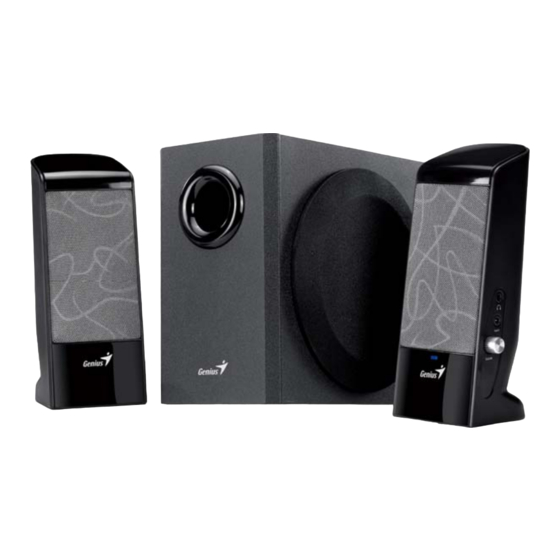
- Page 1 Service Guide SW-J2.1 500 SERVICE GUIDE KEY SYSTEM CORP Version 1.0 Page 1 of 23...
-
Page 2: Revision History
Service Guide SW-J2.1 500 Revision History Version Date Change 06/08/2009 Version 1.0 Page 2 of 23... -
Page 3: Table Of Contents
Service Guide SW-J2.1 500 Table of Contents Revision History………………………………………………………………….2 Table of contents……………………………………………………………...…3 Getting Start…………………………………………………….………………...4 Conventions Used in this Guide…………………………………………….…4 Safety Precautions………………………………………………………………4 Chapter 1. How to Handle Defective Returns……………………………….5 1.2 Problem………………………………………………………………………6 1.2.1 No power,LED (indicator)unlighted……………………………….7 1.2.2 No sound…………………………………………………………….…….8 1.2.3 Right or left channel no sound….……….……….……….……..….……9 1.2.4 Woofer no sound….……….……….……….………….….……….……10 1.2.5 Noise………………………………….…………………………….…..…11 1.2.6 LED indicators no light…………………………….….……………..….12... -
Page 4: Getting Start
Service Guide SW-J2.1 500 Getting Started Conventions Used in the Guide Pay Special Attention: Instructions that are important to remember and may prevent mistakes. Caution: Information that, if not followed, may result in damage to the product. Safety Precautions The following precautions should be observed in handing the speaker described in this guide: Place the speakers on a flat, level and stable surface. -
Page 5: Chapter 1. How To Handle Defective Returns
Service Guide SW-J2.1 500 Chapter 1. How to Handle Defective Returns 1.1 Overview Receiving Defective speaker from customers Verifying problems Proceeding Necessary tests Function NG Function OK Function NG Analyzing possible Malfunction cause Deciding & proceeding the Rectification methods Replace necessary Defective parts Verifying problems Proceeding... -
Page 6: Problem
Service Guide SW-J2.1 500 1.2 Problems Item Problem Description No power,LED (indicator)no light 1.2.1 1.2.2 No sound 1.2.3 Right or left channel no sound 1.2.4 Woofer no sound 1.2.5 Noise 1.2.6 LED indicator no light 1.2.7 Headphone jack output no sound 1.2.8 VR, headphone jack or line-in jack abnormal Version 1.0... -
Page 7: No Power,Led (Indicator)Unlighted
Service Guide SW-J2.1 500 *Attention Please follow the numbered sequence marked within parenthesis given in individual Flow chat in that this is the best-recommended sequence to rectify the problems. 1.2.1 No power,LED (indicator)unlighted No power,LED (indicator)unlighted Problem Analyze Or caused by the following: Defective transformer 1. -
Page 8: No Sound
Service Guide SW-J2.1 500 1.2.2 No sound No sound Problem Or caused by the following defective JK1 in J2.1 500 AMP and JK3 components short-circuited, dry in J2.1 500 CON is not Analyze and IC1, IC2 in J2.1 500 AMP PCB soldered or properly connected identify the... -
Page 9: Right Or Left Channel No Sound
Service Guide SW-J2.1 500 1.2.3 Right or left channel no sound Right or left channel no sound Problem 1. VR,JK2 or JK4 defective in J2.1 500 Driver unit or speaker PCB damaged, dry-soldered CON PCB cable defective or short-circuited 2. Or caused by the following defective loosely connected Analyze and JK1 in J2.1 500 AMP and JK3... -
Page 10: Woofer No Sound
Service Guide SW-J2.1 500 1.2.4 Woofer no sound Problem Woofer no sound J2.1 500 AMP PCB VR2 in damaged, Analyze and Woofer driver unit defective dry-soldered identify the J2.1 /Speaker cable of short-circuited causes 500AMP dry-soldered or defective Repair or replace Repair or replace Repair or replace Solution... -
Page 11: Noise
Service Guide SW-J2.1 500 1.2.5 Noise Problem Noise Filter capacitor/ diode dry-soldered or damaged, pls check EC16, EC2, Or caused by vibration from Driver units damaged Analyze and EC10, EC13, EC5,EC15, D1, D2, too long lead wire of driver Woofer cabinet leaks, identify the... -
Page 12: Led Indicators No Light
Service Guide SW-J2.1 500 1.2.6 LED indicator no light Problem LED indicator no light PCB damaged, dry-soldered or short-circuited 2. R1 in J2.1 500AMP PCB R1defective 3. Poor connection of JK1 in J2.1 500AMP PCB and JK3 in Analyze and J2.1 500CON PCB identify the 4. -
Page 13: Headphone Jack Output No Sound
Service Guide SW-J2.1 500 1.2.7 Headphone jack output no sound Problem Headphone jack no sound JK2 in J2.1 500 CON PCB defective or its related copper foil broken Analyze and identify the causes Solutions Check and replace Version 1.0 Page 13 of 23... -
Page 14: Vr, Headphone Jack Or Line-In Jack Abnormal
Service Guide SW-J2.1 500 1.2.8 VR, headphone jack or line-in jack abnormal Problem VR, headphone jack or line-in jack abnormal Jack: Analyze and JK2 or JK4 in J2.1 500CON PCB Defective VR may cause VR1 in identify the defective J2.1 500CON PCB or VR2 in J2.1 causes SP3 in J2.1 500AMP PCB defective 500AMP PCB having scratching... -
Page 15: Chapter 2. Specification
Service Guide SW-J2.1 500 Chapter 2. Specifications Satellite Normal DESCRIPTION UNIT LIMIT ≧3 RATED OUTPUT POWER @THD 10% SENSITIVITY (1KHz) @RATED O/P POWER 600±60 SENSITIVITY (1KHz) @1W O/P POWER 260±60 MAX INPUT LEVEL@1% THD 350±35 ≦1 DISTOPTION@1kHz FREQUENCY RESPONSE(1KHz -3DB ) LOW 190±20 FREQUENCY RESPONSE(1KHz -3DB ) HI 110±20... -
Page 16: Chapter 3 Block Diagram
Service Guide SW-J2.1 500 Chapter 3 Block diagram Version 1.0 Page 16 of 23... -
Page 17: Chapter 4 Exploded View
Service Guide SW-J2.1 500 Chapter 4 Exploded view Subwoofer Version 1.0 Page 17 of 23... -
Page 18: Right Satellite
Service Guide SW-J2.1 500 Chapter 4 Exploded view Right Satellite Version 1.0 Page 18 of 23... -
Page 19: Left Satellite
Service Guide SW-J2.1 500 Chapter 4 Exploded view Left Satellite Version 1.0 Page 19 of 23... -
Page 20: Chapter 5 Part List
Service Guide SW-J2.1 500 Chapter 5 Part list Woofer Description Part NO port tube, SW2.1 500 EP41510068 port tube, YM777 EP41510065 wooden cabinet, J2.1 500 EP53500J03A driver unit, A-862-3 EP16030073 PCBA, J2.1 500 EPH1P500001 knob, YM230 EP40711187 power switch EP19030008 EP13500056 transformer, 230V 50HZ/10V-1.5A woofer driver unit cloth cover, J2.1 500... -
Page 21: Right Satellite
Service Guide SW-J2.1 500 Chapter 5 Part list Right Satellite Description Part NO cloth grill of satellite, Y036 EP64000187 driver unit, A-50-13 EP16020061 Front panel, Y036 EP40310338 LED cover, KA-814-2.1 EP41610019 EP15500005 PCBA, J2.1 500 94HB Back cover,Y036-2 EP40610401 Knob, J200 EP40711186 VR1, 16KG-B10K-L12F EP1B010084... -
Page 22: Chapter 6 Important Notes
Service Guide SW-J2.1 500 Chapter 6. Important Notes 6.1 Packing requirement for sending the PCB assembly by post PCB assembly is a kind of sophisticated electronic circuit board. Well packing will be required when sending them by post. *Some sophisticated IC components are mounted on the PCB assembly;... -
Page 23: Chapter 7 Schematic Diagram
Service Guide SW-J2.1 500 Chapter 7. Schematic diagram SW-J2.1 500 PCB Version 1.0 Page 23 of 23...
Need help?
Do you have a question about the Genius SW-J2.1 500 and is the answer not in the manual?
Questions and answers