Advertisement
Quick Links
INSTALLATION AND MAINTENANCE INSTRUCTIONS
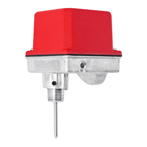
PIBV2 Post Indicator and
Butterfly Valve Supervisory Switch
SPECIFICATIONS
Contact Ratings:
Dimensions:
Maximum Stem Extension:
Operating Temperature Range:
Shipping Weight
Enclosure Rating:
U.S. Patent Number:
IMPORTANT
Please Read Carefully and Save
This instruction manual contains important information on the installation and op-
eration of supervisory switches. Purchasers who install supervisory switches for use
by others must leave this manual or a copy of it with the user. These instructions
apply to System Sensor switches for post indicator and butterfly type valves. Read
all instructions carefully before beginning installation.
Do NOT use this switch in explosive or potentially explosive atmospheres.
Do NOT leave unused wires exposed.
Before installing any supervisory switches in sprinkler systems, be thoroughly fa-
miliar with:
NFPA 72:
Installation, Maintenance and Use of Local Protective
Signalling Systems
NFPA 13:
Installation of Sprinkler Systems, specifically Section 3.17
NFPA 25:
Inspection, Testing and Maintenance of Sprinkler Systems, specifically
Chapters 4 and 5
FIGURE 1:
COVER
TAMPER
SCREWS
TAMPER
PROOF
WRENCH
(P/N WFDW)
ACTUATING
CAM
ACTUATING
LEVER SCREW
NIPPLE SET SCREW
THREADED
3
1
/
˝ D
NIPPLE
4
HEX
WRENCH
(P/N HEXW)
10A @ 125/250 VAC
; 2.5 A @ 24 VDC
⁄
˝ H × 3
⁄
˝ W × 3
⁄
˝ D
1
1
1
4
4
2
4
⁄
˝ (8.0 cm)
5
3
32
32°F to 120°F (0°C to 49°C)
2 lbs.
NEMA Type 3R when mounted with the actuator vertical (cover on top) as tested by Underwriters Laboratories, Inc.
IP54
5,213,205
CAUTION
4
1
/
4
(ASSEMBLED)
SPRING
MOUNTING SCREWS
SWITCH ENCLOSURE
BASE HOUSING
3
1
/
˝ W
2
ACTUATING
LEVER
RETAINING NUT
W0224-00
GENERAL INSTALLATION CONSIDERATIONS
1.
Model PIBV2 is designed for installation in a
so that the actuating lever of the switch engages the target or flag of the valve .
The switch actuating lever is spring loaded against the flag or target of the valve
and is released when the valve moves toward the closed position from the fully
open position. The switch is factory set to indicate an alarm condition when the
target and lever move in the direction toward the conduit entry hole when the
valve closes, but can be reversed if the installation demands (refer to Section 4).
2.
Model PIBV2 is equipped with a removable
locked in place with one set screw. A hex wrench is provided for this feature.
The PIBV2 also includes an adjustable length actuating lever.
3.
The cover is secured with two tamper resistant screws which require a special
key to remove. One key is included with each supervisory switch. Replacement
and additional keys are available (Part No. WFDW).
INSTALLATION INSTRUCTIONS FOR POST INDICATOR VALVES
1.
There are two types of post indicator valves – rising flag and falling flag. In a
rising flag installation, the PIBV2 mounts below the target assembly, as shown in
Figure 2A. Closing the valve raises the target assembly and releases the actuating
lever on the PIBV2. In a falling flag installation, the PIBV2 mounts above the
target assembly (Figure 2B). Closing the valve lowers the target assembly and
releases the actuating lever on the PIBV2.
The PIBV2 is set for falling flag installation. If a rising flag operation is desired,
it is necessary to reverse the action of the switch (See Section 4).
FIGURES 2A. RISING FLAG:
˝ H
2.
If the post indicator valve is predrilled with
plug and go to step 6. If the post indicator valve is NOT equipped with a
NPT mounting hole, it will be necessary to drill and tap the hole.
3.
Position the valve in the fully open position ("OPEN" should appear in the
window) and remove the head and target assembly. In doing so, ensure that the
assembly can be reinstalled with its original adjustment.
1
3825 Ohio Avenue, St. Charles, Illinois 60174
1.800.SENSOR2; Fax: 630.377.6495
www.systemsensor.com
⁄
˝ NPT tapped hole and located
1
2
⁄
˝ NPT pipe nipple which is
1
2
SECTION 1
FIGURE 2B. FALLING FLAG:
TARGET
HEAD
⁄
˝ NPT mounting hole, remove the
1
2
I56-0394-011R
W0213-00
⁄
˝
1
2
04-29
Advertisement

Summary of Contents for System Sensor PIBV2
- Page 1 (Figure 2B). Closing the valve lowers the target assembly and releases the actuating lever on the PIBV2. The PIBV2 is set for falling flag installation. If a rising flag operation is desired, it is necessary to reverse the action of the switch (See Section 4).
- Page 2 Retract the actuating arm and install PIBV2 onto the nipple, orienting the PIBV2 to trip the switch as the valve closes. If the conduit entry is on the wrong ACTUATOR VERTICAL (POINTING UP) side, it will be necessary to reverse the action of the switch (see Section 4). Ap- W0381-00 ply pressure to PIBV2 and tighten set screw to secure the assembly.
- Page 3 Slide the switch enclosure away from the conduit entry toward the actuating pivot arm as far as possible and tighten the 3 screws to secure the enclosure. (Ensure that switch enclosure remains oriented away from the conduit entry as When utilizing switches at voltages greater than 74 VDC or 49 VAC screws are tightened.) , means to provide all-pole disocnnection must be incorporated in the field wiring,...
- Page 4 THREE-YEAR LIMITED WARRANTY System Sensor warrants its enclosed supervisory switch to be free from defects in materi- 12220 Rojas Drive, Suite 700, El Paso TX 79936, USA. Please include a note describing the als and workmanship under normal use and service for a period of three years from date malfunction and suspected cause of failure.


Need help?
Do you have a question about the PIBV2 and is the answer not in the manual?
Questions and answers