Table of Contents
Advertisement
Installation, Operation, and Maintenance
Wired Temperature Sensors
Only qualified personnel should install and service the equipment. The installation, starting up, and servicing of
heating, ventilating, and air-conditioning equipment can be hazardous and requires specific knowledge and training.
Improperly installed, adjusted or altered equipment by an unqualified person could result in death or serious injury.
When working on the equipment, observe all precautions in the literature and on the tags, stickers, and labels that are
attached to the equipment.
April 2020
SAFETY WARNING
BAS-SVX10F-EN
Advertisement
Table of Contents

Related Manuals for Trane Technologies X1351152701

Summary of Contents for Trane Technologies X1351152701
- Page 1 Installation, Operation, and Maintenance Wired Temperature Sensors SAFETY WARNING Only qualified personnel should install and service the equipment. The installation, starting up, and servicing of heating, ventilating, and air-conditioning equipment can be hazardous and requires specific knowledge and training. Improperly installed, adjusted or altered equipment by an unqualified person could result in death or serious injury. When working on the equipment, observe all precautions in the literature and on the tags, stickers, and labels that are attached to the equipment.
- Page 2 Introduction Warnings, Cautions, and Notices Safety advisories appear throughout this manual as required. Your personal safety and the proper operation of this machine depend upon the strict observance of these precautions. The three types of advisories are defined as follows: Indicates a potentially hazardous situation which, if not avoided, could result in WARNING death or serious injury.
- Page 3 Introduction WARNING Personal Protective Equipment (PPE) Required! Failure to wear proper PPE for the job being undertaken could result in death or serious injury. Technicians, in order to protect themselves from potential electrical, mechanical, and chemical hazards, MUST follow precautions in this manual and on the tags, stickers, and labels, as well as the instructions below: •...
-
Page 4: Table Of Contents
Table of Contents General Information ..........6 Product Description . - Page 5 Table of Contents Requesting Temporary Occupancy ......31 Error codes ..........31 Lock Symbol .
-
Page 6: General Information
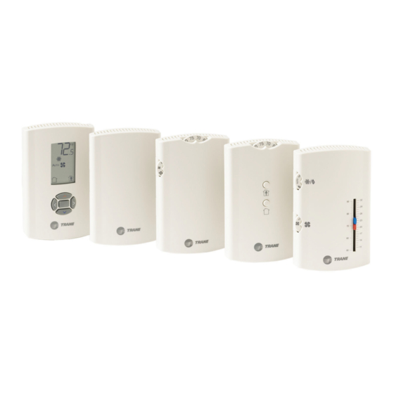
General Information This section provides a description of the wired temperature sensors, as well as part numbers and dimensions. Product Description Note: The information in this manual applies to both factory and field installed versions of Trane wired temperature sensors. ®... -
Page 7: Part Numbers
Part Numbers The following table lists part numbers for each sensor type. Features Global Sensor type Setpoint control System Occupancy LEDs Part number BAYSENS parts Single X1351152701 BAYSENS074A SEN01447 X1351152801 BAYSENS077A SEN01448 Temperature sensors Single X1351152901 BAYSENS075A SEN01449 X1351153001 BAYSENS073A... -
Page 8: Dimensions
General Information Dimensions The following illustration provides specific dimension details. The dimensions are the same for all models. TYP R.07 in (R1.9) mm) 0.31 in (8 mm) TYP 0.24 in (6 mm) 2.9 in (73.5 cm) 1.08 in (27.5 mm) 0.12 in (3 mm) 3.39 in (86 mm) 2.48 in (63 mm) -
Page 9: Pre-Installation
Pre-Installation Pre-Installation This section provides the following pre-installation information: • Location considerations • Height requirements • Mounting surfaces Location Considerations Placement of the sensor is critical to proper operation. When selecting a location, avoid the following: • Areas of direct sunlight •... -
Page 10: Installation And Configuration: Display Sensor
Installation and Configuration: Display Sensor Installation and Configuration: Display Sensor This section provides step-by-step installation instructions for the display sensor (see applicable part numbers for the temperature sensor with LCD display on 7). For installation of all other sensor models, see Read through the pre-installation information(p. - Page 11 Installation and Configuration: Display Sensor 3. Feed the wires through the opening in the back plate. BAS-SVX10F-EN...
-
Page 12: Wiring The Sensor
Installation and Configuration: Display Sensor 4. Hold the back plate against the mounting surface and mark the screw locations. 5. Secure the back plate to the mounting surface using the included hardware. Wiring the Sensor WARNING Hazardous Voltage! Disconnect all electric power, including remote disconnects before servicing. Follow proper lockout/tagout procedures to ensure the power can not be inadvertently energized. -
Page 13: Configuring The Display Sensor
Installation and Configuration: Display Sensor Figure 1. Attaching the terminal block to the pins on the circuit board RJ11 (RJ22 compatible) connection for a Trane service tool Jumper is installed from factory to display local temperature reading. To enable external sensor option, move jumper to “Ext”... - Page 14 Installation and Configuration: Display Sensor 1. Press the configuration button for 3 seconds. Configuration button The display will change to configuration mode. When the sensor is in configuration mode, a wrench symbol appears on the display and the menus are separated by lines, as illustrated below. 1.
- Page 15 Installation and Configuration: Display Sensor • Press to move to the next menu (as illustrated). Setting Configuration options Temperature • Choose Fahrenheit or Celsius • Choose the degree resolution (whole degrees, half degrees, or tenths of degrees) Setpoint single dual setpoint Deadband (available for dual setpoint system only) Note: Deadband refers to the...
- Page 16 Installation and Configuration: Display Sensor Setting Configuration options Note: Not all fan options are available for all systems. auto/off auto/off/ auto/off/low auto/high (on) low/high med/high off/high (on) off/low/high off/low/ no fan options med/high enabled Occupancy (timed override) 1. Review the display to ensure that you have selected the correct configuration options. The example shows a display that has been configured for: •...
-
Page 17: Optional Configuration Features
Installation and Configuration: Display Sensor The following example shows a configured display in operating mode. Display shows the following: • Temperature units (Fahrenheit) • Temperature resolution to tenths of a degree • System setting: Cooling • Fan setting: Auto • Occupied/unoccupied option enabled If an error code exists, it appears at the bottom of the display between the occupancy symbols, as shown below. -
Page 18: Replacing The Cover
Installation and Configuration: Display Sensor 1. Verify that the sensor is in operating mode and at the home screen. 2. Choose a setting to lock or unlock: • Select the setpoint by pressing the up or down arrow. Setpoint • Select the system menu by pressing the center button. Use the left or right arrow to choose the setting. - Page 19 Installation and Configuration: Display Sensor 2. Secure the cover by installing the security screw into the bottom of the cover. Security screw BAS-SVX10F-EN...
-
Page 20: Installation: All Models Other Than The Display Sensor
Installation: All Models Other Than the Display Sensor Installation: All Models Other Than the Display Sensor This section provides step-by-step installation instructions for all sensor models other than the display sensor. (For installation of the display sensor, see 10.) Read through the pre-installation information before proceeding with the installation. - Page 21 Installation: All Models Other Than the Display Sensor Note: If present, remove the security screw before removing the cover. 3. Remove the circuit board by pressing the thumb catch on the left side of the board. Use the terminal block to lift the circuit board from the back plate. Thumb catch Terminal 4.
- Page 22 Installation: All Models Other Than the Display Sensor 6. Secure the back plate to the mounting surface using the included hardware. 7. Feed the wires through the opening in the circuit board. 8. Replace the circuit board by sliding the right side of the board under the two catches on the right side of the back plate, while aligning slot on board with tab on back plate.
-
Page 23: Installing The Comm Module (Optional)
Installation: All Models Other Than the Display Sensor Installing the COMM Module (optional) An optional COMM module is available that provides a local RJ22 connection to a Trane service tool for maintenance use. It must be ordered separately. Install the COMM module before wiring the sensor: 1. -
Page 24: Changing The Setpoint Thumb Wheel (Optional)
Installation: All Models Other Than the Display Sensor Changing the Setpoint Thumb Wheel (optional) Sensors with temperature setpoint control have pre-installed Fahrenheit setpoint thumb wheels. A Celsius setpoint thumb wheel is included with these sensors. An optional hot/cold setpoint thumbwheel can be ordered separately. To change the thumb wheel: 1. -
Page 25: Replacing The Cover
Installation: All Models Other Than the Display Sensor Replacing the Cover To replace the cover: 1. Hook the cover over the top of the back plate. Apply light pressure to the bottom of the cover until it snaps in place. 2. -
Page 26: Operation
Operation Operation This section describes sensor operations. Changing Temperature Settings To change temperature settings: • For sensors with temperature setpoint thumb wheels (located on top of the sensor), rotate the thumb wheel to the desired temperature setting. Note: If you need to change or replace a thumb wheel, see “Changing the Setpoint Thumb Wheel (optional),”... -
Page 27: Selecting Temporary Occupancy (Timed Override)
Operation Selecting Temporary Occupancy (Timed Override) Temporary occupancy (timed override) is available on some sensors. Temporary occupancy can be selected to adjust temperature, fan, or heat/cool settings after the system has changed to unoccupied mode. System control will revert to unoccupied after a pre-determined time period. Note: Not all systems support the occupancy function. -
Page 28: Service Pin Request
Operation Service Pin Request Some sensor models can communicate a service pin request to their connected unit controller. Sensors with Occupied/Unoccupied Buttons To initiate a service pin request, press the Occupied button (Figure 2, p. 27) for 10–25 seconds. The following occurs: Space temperature output is driven to 10 (nominal). -
Page 29: Star(*)/Double Star(**) Function
Operation Star(*)/Double Star(**) Function The star/double star function is available on sensor models with thumb wheels and on the display sensor. Note: Consult the appropriate unit controller documentation for information about this function. Sensors with Thumb Wheels Turning the thumb wheel clockwise makes the star (*) visible; turning it counter-clockwise makes the double star(**) visible (see Figure •... -
Page 30: Display Sensor Operation
Operation Display Sensor Operation This section describes display sensor operation. Figure 5 shows an example of a display sensor that has been configured and is in operating mode. Figure 5. Display sensor in operating mode Temperature System settings Fan settings Occupancy indicator/Error code Keypad Changing Temperature Settings... -
Page 31: Changing System Settings
Operation Changing System Settings 1. From the home screen, press . The system setting menu Indicates that the system is in cooling mode. appears. Indicates that the system is in heating mode. 2. Press to choose the desired system setting. 3. -
Page 32: Maintenance And Troubleshooting
Maintenance and Troubleshooting Maintenance and Troubleshooting This section describes sensor features that can be used for maintenance and troubleshooting. LEDs Some sensor models have LEDs. They are located on the front cover and convey the following information: The red service LED indicates that service is needed. Service LED (red) •... -
Page 33: Measuring Output Resistance
Maintenance and Troubleshooting Measuring Output Resistance Measure output resistance as follows, according to sensor type. Display Sensors For display sensors, measure the outputs for zone temperature, setpoints, heat setpoint, and system/fan mode as described: 1. Ensure that the GROUND (terminal 10) and the SIGNAL COMMON (terminal 2) wires share a common ground with the transformer. - Page 34 Maintenance and Troubleshooting Table 1. Resistance measurements for zone temperature and setpoints Nominal zone temperature Nominal setpoint and heating Zone or setpoint temperature output resistance setpoint output resistance 938 55°F (12.8°C) 17.47 k 792 60°F (15.6°C) 15.3 k 695 ...
-
Page 35: Cleaning The Sensor
Maintenance and Troubleshooting Cleaning the Sensor NOTICE: Equipment damage! Spraying glass cleaner or any other solution directly on the sensor may damage it. You can clean the sensor by applying glass cleaner to a soft, non-abrasive cloth, and gently wiping the face, including the buttons and LCD display. -
Page 36: Wiring Diagrams
Wiring Diagrams Each wiring diagram is identified by sensor part number (see “Part Numbers,” p. 7 for reference.) For wiring information for the display sensor, see Figure 1, p. X1351152701 R1, 1.5 kΩ Timed Timed override override thermistor, Ω Unoccupied... -
Page 37: Temperature Sensors With Fan Control
Wiring Diagrams X1351153001 R1, 1.5 kΩ Zone Timed Timed override RT1 thermistor, temperature override On SW1 Ω 10 k at 25°C Cancel SW2 Signal common Dwg source: 3270 3438 Temperature sensors with fan control X1379084501 R9, 1.5 kW R11, zero W Zone Timed Timed... - Page 38 Wiring Diagrams X1379085101 R9, 1.5 kW R11, zero W Timed Zone Timed override temperature override On SW3 Thermistor, Cancel SW4 10 k at 25°C Signal common Note 1: Temperature Calibration Pot 1 is Setpoint Cool setpoint (CSP) Pot 1 (see Note 1 factory Pot 5,...
- Page 39 Wiring Diagrams X1379084101 RT1 thermistor, Zone R11, zero W 10 k at 25°C temperature Signal common Note 1: Temperature Calibration Pot 1 is setpoint Cool setpoint (CSP) Pot 1 (see Note 1 factory Pot 5, calibrated. 1 kW Mode Field (Fan switch) adjustment voids...
-
Page 40: Temperature Sensors With Fan And System Control
Wiring Diagrams Temperature sensors with fan and RT1 thermistor, Zone Ω R9, zero Ω 10 k at 25°C system control temperature Signal common X1379084701 Note 1: Calibration Cool setpoint Pot 1 and Cool setpoint (CSP) Pot 1 (see Note 1 Pot 4, Pot 2 are 1 kΩ... - Page 41 Wiring Diagrams X1379083701 RT1 thermistor, Zone R11, zero W 10 k at 25°C temperature 1 Signal common Note 1: Calibration Cool setpoint Cool setpoint (CSP) Pot 1 (see Note 1 Pot 1 and Pot 4, Pot 2 are 1 kW Mode factory (Sys/Fan switch)
- Page 42 Wiring Diagrams X1379083901 RT1 thermistor, R11, zero W Zone 10 k at 25°C temperature Signal common Note 1: Temperature Calibration Pot 1 is setpoint Cool setpoint (CSP) Pot 1 (see Note 1 factory Pot 5, calibrated. Mode 1 kW Field (Sys/Fan switch) adjustment voids...
-
Page 43: Optional Comm Module
Wiring Diagrams Optional COMM module X1365146702 COMM Module 1 (–) 2 (+) BAS-SVX10F-EN... -
Page 44: Specifications And Agency Compliance
Specifications and Agency Compliance Specifications Sensor operating temperature From 32°F to 122°F (0°C to 50°C) Storage temperature From -40°F to 185°F (-40°C to 85°C) Storage/operating humidity range 5% to 95% relative humidity (RH), noncondensing Thermistor accuracy 0.2°C at 25°C, 1% Display sensor: 50°F to 89.6°F (10°C to 32°C) Setpoint functional range All other sensors: 45°F to 95°F (7.2°C to 35°C) -
Page 45: Ce Declaration Of Conformity
Specifications and Agency Compliance CE Declaration of Conformity Manufacturer: Trane, 4833 White Bear Parkway, Saint Paul, MN 55103, USA Product: Wired display sensor Model number: X1379088601, X1379088604, X1379088605 The manufacturer hereby declares that the product conforms to the following: Electromagnetic Emission: Council Directive 89/336/EEC) EN61326-1:2006, Class B limit Radiated EN55011:2006, Class B limit... - Page 48 Trane - by Trane Technologies (NYSE: TT), a global climate innovator - creates comfortable, energy efficient indoor environments for commercial and residential applications. For more information, please visit trane.com or tranetechnologies.com. Trane has a policy of continuous product and product data improvement and reserves the right to change design and specifications without notice.
Need help?
Do you have a question about the X1351152701 and is the answer not in the manual?
Questions and answers