Nordica LNK15 EVO User Manual

Nordica LNK15 EVO User Manual

Down-fired boilers

Advertisement

Quick Links

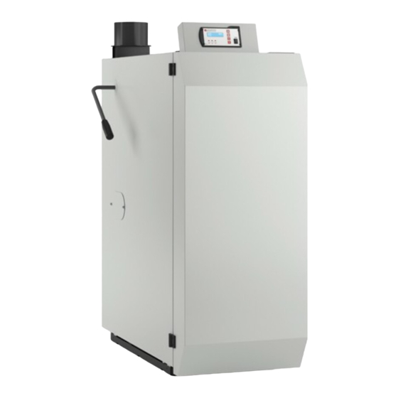
down-fired boilerS USer MAnUAl
UK
iTAliAno
lnK15 eVo - lnK20 eVo
lnK30 eVo - lnK40 eVo
MADE
IN
ITALY
design & production
007291003 - 000

Advertisement

Table of Contents
loading

Summary of Contents for Nordica LNK15 EVO

  • Page 1 USer MAnUAl iTAliAno lnK15 eVo - lnK20 eVo lnK30 eVo - lnK40 eVo MADE ITALY design & production 007291003 - 000...
  • Page 2 ENGLISH...
  • Page 3: Table Of Contents

    ATTENTION sUrfACEs CAN BECOME VEry hOT! ALWAys UsE PrOTECTIVE gLOVEs! During combustion, thermal energy is released that significantly increases the heat of surfaces, doors, handles, controls, glass, exhaust pipes, and even the front of the appliance. Avoid contact with those elements if not wearing protective clothing (protective gloves included).
  • Page 4: Warnings

    We thank you for having chosen our company; our product is a great heating solution developed from the most advanced technology with top quality machining and modern design, aimed at making you enjoy the fantastic sensation that the heat of a flame gives, in complete safety. The purpose of these instructions is to help you become familiar with the operation, maintenance and care of the system.
  • Page 5: Safety

    safety Š The aPPlIance may be used by chIldren 8 years of age or older and IndIvIduals WITh reduced PhysIcal, sensory, or menTal caPacITIes or WIThouT exPerIence or The necessary knoWledge, ProvIded ThaT They are suPervIsed or have receIved InsTrucTIons on safe use of The aPPlIance and ThaT They undersTand The InherenT dangers.
  • Page 6 repairing and performing maintenance on this system. Š The instructions contain important information for correct assembly, operation, personal safety and protection of the boiler system. Š assembly and installation operations can be performed only by qualified and licensed heating and installation specialists.
  • Page 7: Commissioning And Instructions

    commissioninG anD instructions The boiler must be commissioned and the operator trained exclusIvely by QualIfIed and lIcensed Personnel or by an auThorIsed servIce cenTre Incorrect operation may result in additional costs which are not covered by the warranty. manaGement anD monitorinG • IT Is forbIdden To leave chIldren unaTTended nexT To The boIler When In oPeraTIon.
  • Page 8: Warranty And Responsibilities

    warranty anD responsibilities The warranty is only valid if the products have been installed and used correctly. The boiler must be installed in a dry room. The appliance must be used with a return temperature > 60°c for the warranty to be valid. The Warranty conditions can be found on the following website: https://www.lanordica-extraflame.com/en/solutions/guarantee-terms the warranty is voiD also in the followinG cases:...
  • Page 9: Installation

    installation system reGulations for Germany only before installing the boiler, it is necessary to obtain the approval of the main district chimney sweep authorised to submit a chimney calculation. The appliance must be installed in closed heating systems, that have been installed in accordance with current regulations and with the current state of the art.
  • Page 10: Chimney Flue

    chimney flue the sizing, installation and connection of the chimney flue to the boiler must be carried out by an authorised company of master chimney sweepers according to european, national and local regulations. The flue must develop a sufficient draught to convey and transport combustion smoke outdoors at all operating speeds. It is important to have an adequately sized self-sufficient flue for the boiler to operate correctly.
  • Page 11: Chimney

    - have the system repaired. The system must be commissioned by the installing company (specialising in the construction of heating systems) or by an authorised la nordica spa service centre. This must be documented in a commissioning report. It is necessary to check that all system components have been installed correctly and that all control and safety devices are working properly and are correctly set.
  • Page 12: Permitted Fuels

    If the system is not commissioned by legally qualified and authorised personnel, the warranty will be void. The prerequisites for trouble-free operation are: - Periodic cleaning of the boiler - good fuel quality; - constant flue draught; - a sufficient supply of fresh air of at least 4 m³/h for 1 kW in the installation room; - built-in and regulated draught regulator.
  • Page 13: Information On The Boiler

    information on the boiler The lnk-evo boiler is a wood gasification boiler with built-in differential control for buffer tank loading by means of a sensor. all operating parameters are preconfigured in the control. only the primary and secondary air positions need to be adapted to the standard fuel.
  • Page 14: Technical Specifications

    technical specifications lnK 15 evo lnK 20 evo lnK 30 evo lnK 40 evo boiler type 17,3 kW 21 kW 29 kW 37 kW nominal heat output 89,0 % 89,3 % 89,9 % 90,5 % efficiency at nominal heat output of the boiler 78 l 78 l 105 l...
  • Page 15: Dimensions

    Dimensions dImensIons in mm lnK 15 evo lnK 20 evo lnK 30 evo lnK 40 evo 1320 1320 1320 1320 1060 1060 1060 1060 1320 1320 1320 1320 1200 1200 1200 1200 1460 1460 1460 1460 1565 1565 1565 1565 1430 1430 1430...
  • Page 16: Spacing

    spacinG manDatory condensation-proof “T” fitting with inspection plug minimum dIsTances in mm dIsTanZe minime in mm lnK 15 evo lnK 15 evo lnK 20 evo lnK 20 evo lnK 30 evo lnK 30 evo lnK 40 evo lnK 40 evo minimum heIghT of the room in mm alTeZZa minima della stanza in mm lnK 15 evo...
  • Page 17: Identification Of Components

    iDentification of components 1” gas female connection of the boiler safety unit DiGital Display smoke discharge outlet 150 mm system Delivery 1”1/2 gas female connection smoke suction 1/2” female gas sump for Dsa probe 3/4” female gas connection Dsa integrated system inlet 3/4”...
  • Page 18: Safety Heat Exchanger And Automatic Thermal Discharge Valve Dsa

    safety heat exchanGer anD automatic thermal DischarGe valve Dsa The safety heat exchanger of the boiler must be equipped with a tested and certified thermal discharge valve. If the temperature of the boiler exceeds 95°c, the cold water supply is activated to prevent the boiler temperature from rising even more. The water side connection can be made only by a qualified technician, who must make sure that the water supply is sufficient and meets the specifications indicated below.
  • Page 19: Boiler Assembly

    boiler assembly Disassembly / introDuction / assembly The product is delivered almost completely pre-assembled. only the lever for cleaning the heat exchanger and the fan unit needs to be installed. Disassembly depending on the conditions of the room in which the boiler is installed, some parts of it may be disassembled differently for transport purposes.
  • Page 20: Direction Of Smoke Fan

    Direction of smoKe fan The forced draught smoke fan, complete with smoke fitting, is supplied disassembled from the boiler. during installation, the fan is secured to the discharge flange of the boiler together with the fastening nuts and perimeter gasket. To facilitate installation, the smoke inlet can be installed in different positions, with the option to rotate it by 180°.
  • Page 21 Direction of rotation anD components The possible directions of rotation of the exhaust flange are shown below. smoke exhaust system 45°/90° elbow with cleaning opening measuring opening (30 cm distance from the nozzle) draught regulator existing masonry chimney flue chimney inspection opening ENGLISH...
  • Page 22: Installing The Lever For Cleaning The Heat Exchanger

    installinG the lever for cleaninG the heat exchanGer remove the external casing to access the heat exchanger cover. loosen the wing nuts and remove the heat exchanger cover. Insert the flange covering the handle fixing hole behind the side panel of the outer boiler casing. Insert the lever and slide it into the empty pipe of the heat exchanger cleaning system.
  • Page 23: Water Side Connection

    water siDe connection The connection of the boiler to the heating network (delivery and return) must be made with at least the following pipe sections: lnk 15 evo 28 mm lnk 20 evo 28 mm lnk 30 evo 35 mm lnk 40 evo 35 mm lime, corrosion and rust sludge interfere with the operation of the heating system.
  • Page 24: Open Vessel Installation

    open vessel installation. the DiaGrams are purely inDicative, therefore they Do not have DesiGn value. InsTallaTIon, relaTIve sysTem connecTIons, commIssIonIng and verIfIcaTIon of correcT oPeraTIon musT be carrIed ouT correcTly by ProfessIonally QualIfIed and TraIned Personnel In full comPlIance WITh currenT naTIonal, regIonal, ProvIncIal and munIcIPalITy regulaTIons In The counTry Where The aPPlIance Is InsTalled.
  • Page 25: Closed Vessel Installation

    closeD vessel installation. the DiaGrams are purely inDicative, therefore they Do not have DesiGn value. InsTallaTIon, relaTIve sysTem connecTIons, commIssIonIng and verIfIcaTIon of correcT oPeraTIon musT be carrIed ouT correcTly by ProfessIonally QualIfIed and TraIned Personnel In full comPlIance WITh currenT naTIonal, regIonal, ProvIncIal and munIcIPalITy regulaTIons In The counTry Where The aPPlIance Is InsTalled.
  • Page 26: Anti-Condensation Mixing Valve For 60°C Recirculation Circuit

    anti-conDensation mixinG valve for 60°c recirculation circuit (can be supplied as an optional accessory). The anti-condensation mixing valve is used in solid combustion heating devices and boilers since it prevents the return of cold water into the heat exchanger. sections 1 and 3 are always open and, together with the pump installed on the return (r), they guarantee circulation of water inside the heat exchanger of the biomass boiler (down-fired boiler).
  • Page 27: Electrical Connection

    (see photo marked in red) the proDuct must be installeD anD connecteD by qualifieD personnel in compliance with current reGulations. (see chap. sPecIal WarnIngs). norDica s.p.a. shall not be helD liable for unauthoriseD proDuct moDifications as well as use of non-oriGinal spare parts.
  • Page 28 boiler wirinG DiaGram ENGLISH...
  • Page 29: Boiler Operation

    boiler operation installation before starting the boiler, it is necessary to follow this check list: • boiler + installed accessories; • flue gas connection installed in accordance with current regulations; • boiler aligned by means of the adjustable feet; • system filled and bled in accordance with current regulations;...
  • Page 30: First Start-Up

    first start-up The first IgnITIon requires a special approach. It differs from normal operation, as described below, because the inside of the boiler and the refractory panels are still free of ash residue. all air intakes inside the combustion chamber (except for the nozzle stone) must be clogged over time to ensure clean and efficient operation. To do this, proceed as follows: line upper...
  • Page 31: Heating (Normal Operation)

    heatinG (normal operation) before heating with wood, it is necessary to consider the storage tank temperature to load the boiler with the correct amount of fuel. make sure that there is sufficient thermal capacity in the storage tank! Please pay attention to the heat demand of your system in relation to the external temperatures, especially in transition periods, to avoid overheating the system.
  • Page 32 close the upper and lower doors of the boiler. Place some paper or cardboard in front of the logs to help them light. start the iGnition process from the dIsPlay The IgnITIon process must be activated from the control display, only afTer The boIler has been loaded. 25°C 20 °C Temp.
  • Page 33 “half-close” the ignition door 1 cm after lighting the cardboard or paper, leave the ignition door ajar with a gap of about 1 cm. if the Door is fully closeD, the flame will Go out. if the Door remains fully open, smoKe can escape into the boiler room! close the ignition door and the boiler panelling door.
  • Page 34: Adding Fuel

    information on the safety Devices: at a boiler temperature of 85°c, the boiler switches to overheating mode or to modulation mode. This is an attempt to “slow down” combustion, in order to prevent a further rise in temperature, without stopping combustion. When the boiler temperature reaches 90°c, the smoke fan is deactivated in order to stop the combustion air and thus stifle combustion.
  • Page 35: Control Display

    control Display The control display regulates combustion and boiler output according to the water temperature in the exchanger and the smoke temperature. The prerequisite for correct regulation is a correctly sized hydraulic system and chimney flue. service sWITch off: press the switch to o press the switch to i sWITch on: When the appliance is switched on, the software version appears for about 5 seconds.
  • Page 36 scrollinG throuGh the menu 25°C 20 °C Press the menu key Temp. Temp. smoke WaTer 1) IgnITIon (on/off) use the arrow keys 2) manual (on/off) to move 3) boIler PumP TemPeraTure (seT degrees) from one item to another 4) acousTIc alarm (on/off) 5) language (selecT language) 6) buffer Tank on (on/off) 7) manufacTurer’s seTTIngs (yes/no)
  • Page 37: Error Messages

    error messaGes To ensure trouble-free operation, the appliance is equipped with a series of safety elements. In the event of a fault, an acoustic alarm signal is given. important: a qualifieD technician must checK the causes of all problems with the boiler. failures DurinG operation error message ultimate cause...
  • Page 38 faults DurinG operation problem possible causes - check return temperature (min. 60 °c) - check flue draught (15 Pa) - check room air inlet supply smoke leak - check wood moisture (not above 20 % and not below 12 %) - logs too large - check smoke channel development and cleanliness - set fan power based on fireplace draught...
  • Page 39: Chimney Sweep Button And Measuring Emissions

    chimney sweep button anD measurinG emissions boiler measurement (if applicable by current reGulations) While the designated auditor is performing the measurements, it is convenient for the system installer to be present. If system problems are encountered, the installer can intervene immediately in total safety. The measuring sequence must be strictly complied with! PreParaTIon: - completely clean boiler (important: heat exchanger pipes) - Perfectly clean smoke duct and chimney flue...
  • Page 40: Cleaning

    cleaninG to clean the boiler, the system must have cooleD Down below 60°c. the system must be put out of service DurinG cleaninG operations. attention rIsk of fIre due To hoT ashes. alWays be careful WITh ashes as They may conceal burnIng embers. do noT use sTandard vacuum cleaners.
  • Page 41 cleaning and maintenance table application daily Weekly monthly yearly heat exchanger cleaning lever user (10 cycles) removal of ashes from the lower user combustion chamber check nozzle openings user removal of ashes from the upper user combustion chamber check system pressure user clean heat exchanger pipes user...
  • Page 42: Daily Cleaning

    Daily cleaninG use the cleaning lever The lever mechanism on the left side of the boiler is used in order to clean the heat exchanger pipes. move the cleaning lever up and down for the turbulators to move up and down inside the pipes. This movement must be made 10 times in a row (see figure 1).
  • Page 43: Weekly Cleaning

    weeKly cleaninG The following conditions must be ensured in order to execute weekly cleaning of the boiler: • boiler moDe: boiler in standby mode - off • boiler temperature below 50 °c It is not possible to execute cleaning if the boiler is not in “off mode”. If the boiler is operating, it cannot be stopped (wait until combustion has ended automatically!).
  • Page 44: Monthly Cleaning

    monthly cleaninG The following conditions must be ensured in order to execute monthly cleaning of the boiler: • boiler moDe: boiler in standby mode - off • boiler temperature below 50 °c IT Is noT PossIble To execuTe cleanIng If The boIler Is noT In “sTandby mode - off”. If the boiler is operating, it cannot be stopped (wait until combustion has ended automatically!).
  • Page 45: Annual Cleaning

    annual cleaninG The following conditions must be ensured in order to execute annual cleaning of the boiler: • boiler moDe: boiler in standby mode - off • boiler temperature below 30 °c • no voltage on the boiler - Turn the main switch from i to o, disconnect the mains power supply. IT Is noT PossIble To execuTe cleanIng If The boIler Is noT In “sTandby mode - off”.
  • Page 46 checK the smoKe DischarGe system seal IT Is necessary To check ThaT The PerImeTer seal beTWeen The fan body on The boIler and The fan moTor Is InTacT and comPleTe. clean the combustion chamber • open the uPPer and cenTre door. •...
  • Page 47: Disposal

    DiSpoSal Smaltimento Informazioni per la gestione di rifiuti di apparecchiature elettriche ed elettroniche contenenti pile e accumulatori Questo simbolo che appare sul prodotto, sulle pile, sugli accumulatori oppure sulla loro confezione o sulla loro documentazione, indica che il prodotto e le pile o gli accumulatori inclusi al termine del ciclo di vita utile non devono essere raccolti, recuperati o smaltiti assieme ai rifiuti domestici.
  • Page 48 La NORDICA S.p.A. Via Summano, 104 36030 - MONTECCHIO PRECALCINO (VI) - ITALY   +39.0445.804000 -  +39.0445.804040 -  info@lanordica.com - www.lanordica-extraflame.com TO FIND THE SERVICE CENTRE NEAREST TO YOU TO FIND THE SERVICE CENTRE NEAREST TO YOU...

This manual is also suitable for:

Lnk20 evoLnk30 evoLnk40 evo

Table of Contents