
Subscribe to Our Youtube Channel
Related Manuals for APG MND


Summary of Contents for APG MND
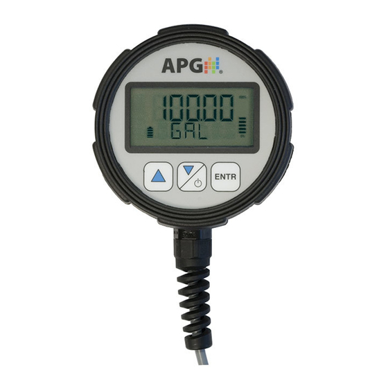
- Page 1 AUTOMATION P R O D U C T S GROUP, INC. Operator’s Manual Modbus Network Display DOC. 9003708 Rev. A, 6/15 Automation Products Group, Inc. 1.800.561.8187 information@itm.com www. .com...
-
Page 2: Table Of Contents
Rev. A, 6/15 Table of Contents Warranty....................... 3 Display Wiring ....................4-6 Using the MND ..................... 7 Access Modes ....................... 8 Menu Flow Chart ....................9 Units of Measure ....................10 Enter Button Function ..................10 Advanced Settings ..................11-12 Auto-Off ......................11 Decimal Place .................... -
Page 3: Warranty
No representation or warranty, express or implied, made by any sales representative, distributor, or other agent or representative of APG which is not specifically set forth herein shall be binding upon APG. APG shall not be liable for any incidental or consequential damages, losses or expenses directly or indirectly arising from the sale, handling, improper application or use of the goods or from any other cause relating thereto and APG’s liability hereunder, in... -
Page 4: Display Wiring
RS-485 A+ White White White RS-485 B- Green Green Green 4-20 mA Black Relay Power *No connection for MND’s with internal batteries 4-pin MM12 No Output 4-20 mA Switchable Power 1 Brown +24 VDC* +24 VDC Relay Power 2 White... - Page 5 DC Ground DC Ground 4 Black RS-485 B- RS-485 B- RS-485 B- RS-485 B- 5 Grey Analog Out *No connection for MND’s with internal batteries 6-pin Tajimi No Output 4-20 mA Switchable 0-3 VDC Power +24 VDC* +24 VDC Relay Power...
- Page 6 Rev. A, 6/15 8/C Cable 2 NO/NC 0-3 VDC & 2 (22 AWG) Relays Relays +24 VDC DC Ground Black Black RS-485 A+ White White RS-485 B- Green Green 0-3 VDC Orange NO/NC1 Yellow Yellow Com1 Blue Blue (Shared) Com2 Brown NO/NC2 Orange...
-
Page 7: Using The Mnd
Function within Setup Menu: press to cycle upward through menu options or to increase mode setting values. Decrease/Power Button Function in Operating Mode: press and hold for 1 second to power on or off the MND. Function within Setup Menu: press to cycle downward through menu options or decrease mode setting values. -
Page 8: Access Modes
Rev. A, 6/15 *Access Modes The MND has several operating modes which will limit or lock access to the setup menus. Refer to the mode descriptions at the bottom of the page for more information. To access the operating mode setting, follow the steps below. -
Page 9: Menu Flow Chart
Rev. A, 6/15 Menu Flow Chart Main Menu COMM bAUd R PARITY STOPbT AL SET OUTPUT C TYPE AH SET SENAdR AL CAL NUMSEN AH CAL REGNUM T1TYPE FUNCTN T1REAd REGTYP T1 WIN SCANRT T2TYPE WRITE T2REAd AdRCHG T2 WIN EXIT EXIT SENLAb... -
Page 10: Enter Button Function
Rev. A, 6/15 UNITS (Units of Measure Label) • Allows the user to select the unit of measure label that will appear on the lower display line. Options: CU FT (Cubic Feet) LITERS (Liters) MCU FT (Million Cubic Feet) CU IN (Cubic Inches) GALLON (Gallons) bARREL (Barrels) CU M (Cubic Meters) -
Page 11: Advanced Settings
(Decimal Place): defines where the decimal point will be displayed within the reading. NOTE: most APG sensors have the ability to set the number of decimal places of the readings being sent to the MND. Refer to the sensor manual for more information. - Page 12 Battery or RST Battery options. The Internal Battery option is used to monitor the voltage of a battery powered MND. The RST Battery option is used to monitor the supply voltage of an RST-5000 module acting as the master device.
- Page 13 (Trip 1&2 Type): determines the basic functional logic of the relay outputs as described in the Trip Type descriptions on pages 14-16. NOTE: the MND’s Telecom Relays are rated for a maximum switched load of 5 Amps at 240 VAC or 220 VDC.
- Page 14 Rev. A, 6/15 Trip Type Descriptions TRIP TRIP NEAR READING WINDOW READING ZERO The output will activate READING whenever the reading is less than the Trip Reading setting. TRIP TYPE 0 EXCLSV NEAR (Exclusive): The output will activate whenever the reading is less than the Trip Reading TRIP TYPE 1 OR greater than the Trip...
- Page 15 Rev. A, 6/15 INCLSV (Inclusive): TRIP TRIP READING WINDOW READING ZERO The output will activate READING whenever the reading is greater than the Trip Reading and less than the Trip Reading + Trip TRIP TYPE 0 Window. NEAR H FAR (Hysteresis Far): The output will activate when the reading...
- Page 16 (in seconds). NOTE: when using the Timed Interval in conjunction with the Auto-Off feature, the MND will wake (power on) at each Interval and will remain powered on for the duration of the relay On-Time regardless of the Auto-Off setting.
- Page 17 Switchable Power Source Output Option* (refer to Switchable Power wiring on pages 4-5) This option is designed to allow an internal battery powered MND to share its battery power (via relay T1) with one of APG’s Modbus sensors (MNU, MPX, or PT series) to create a simple yet complete monitoring system.
- Page 18 (acting as the master device). SETUP : sets the MND to act operate as a “slave” device in order to be programmed using the APG Modbus software. NOTE: the Sensor Address parameter (see below) is used to set the MND’s own sensor address when operating in Setup mode.
- Page 19 Rev. A, 6/15 NUMSEN (Number of Sensors): sets the number of sensors to be monitored. When using the MND to display readings from multiple sensors, the sensor addresses must begin at 1 and increment sequentially (see note above). REGNUM (Register Number): sets the register number to be displayed. The readings of APG sensors are stored in register 30303.
- Page 20 Rev. A, 6/15 WRITE : allows the MND, operating in Master mode, to write a value to a specific holding register of a specific sensor. When Write is selected, the MND will guide you through the following steps: Sensor Address: set the address number of the target sensor.
- Page 21 Percent Full mode. NOTE: when controlling one of the MND’s outputs with a sensor setup to display in Percent Full mode, the settings controlling the output need to be entered based on the underlying readings and not the displayed percentage value.
- Page 22 The software used to program the MND is the same software used to program any of APG’s line of Modbus sensors (MNU, MPX, PT series). Interfacing with the software also allows the user to save MND configurations to a PC, or to write a previously saved configuration back to the MND (see page 25).
- Page 23 RS-485 to RS-232 converter being used. Step 7: Select MND Step 8: Once all the changes have been made, click “Save Config” then click “Close” Step 9: Click on “Sensor 1 “ to enter the programming window for the MND. 1.800.561.8187 information@itm.com www. .com...
- Page 24 “Send” button to write the new value to the MND. Step 11: To change multiple parameters, individually click on the values you wish to change, enter the desired values, then click the “Send All”...
- Page 25 “Save” Recalling a Saved Settings Configuration To upload a previously saved settings configuration to the MND, click on “File”, then se- lect “Load Mode Values”. Choose a file you wish to upload, then click “Open”. This will load the parameter values into the software. Click the “Send All” button at the bottom of the window to write the parameters to the MND.
- Page 26 Rev. A, 6/15 Communications Setup Examples For APG sensors, the sensor readings are stored in register 303, which is an unsigned 32-bit register. MND master displaying readings from a single sensor (address 1): C-Type = Master Number of Sensors = 1...
-
Page 27: Auto-Off
Rev. A, 6/15 Resetting the MND to factory defaults Simultaneously press and hold the Decrease/Power button and Enter button for approximately 5 seconds. This will bring up the 3 digit operating mode number. Change the mode number to 125 and press the enter button. This will reset all parameter values... -
Page 28: Specifications
Rev. A, 6/15 Specifications Environmental: Housing: IP67 Storage Temp: -40 to 160 F (-40 to 71 Operating Temp: 0 to 160 F (-18 to 71 Electrical: Batteries: 9 V Lithium or 3.6 V Lithium (no outputs) External Power: 9-28 Vdc Physical: Case Material: injection molded material EMI-X PDX-W-88341 4-20 mA Output:... - Page 29 Rev. A, 6/15 MNU Series Ultrasonic nput Registers (0x04): Register Type Returned Data 30300 Raw Distance/Level Reading (in mm) 30302 Temperature Reading (in C, signed) 30303-30304 Calculated Reading (in selected units, no decimal) Holding Registers (0x03): Register Type Description Value Range 40400 Device Address 1 to 255...
- Page 30 Rev. A, 6/15 MPX Series Magnetostrictive Input Registers (0x04): Register Type Returned Data 30300 Raw Top Float Reading (in mm, unsigned) 30301 Raw Bottom Float Reading (in mm, unsigned) 30302 Temperature Reading (in C, signed) 30303-30304 Calculated Top Float Reading (in selected Units) 30305-30306 Calculated Bottom Float Reading (in selected Units) Holding Registers (0x03):...
- Page 31 AUTOMATION P R O D U C T S GROUP, INC. Automation Products Group, Inc. To order additional copies of this manual, ask for APG document number 9003708 Rev. A, 6/15 1.800.561.8187 information@itm.com www. .com...
Need help?
Do you have a question about the MND and is the answer not in the manual?
Questions and answers