
Subscribe to Our Youtube Channel
Related Manuals for comoc CS700


Summary of Contents for comoc CS700
- Page 1 USE AND MAINTENANCE MANUAL CS700 H CS800 H ED. 11-2012 ORIGINAL INSTRUCTIONS Doc. 10031936 Version...
- Page 2 The descriptions contained in this document are not binding. The company therefore reserves the right to make any modifications at any time to elements, details, or accessory supply, as considered necessary for reasons of improvement or manufacturing/commercial requirements. The reproduction, even partial, of the text and drawings contained in this document is prohibited by law.
-
Page 3: Table Of Contents
CONTENTS ON CONSIGNMENT OF THE MACHINE................................5 INTRODUCTORY COMMENT .................................... 5 IDENTIFICATION DATA ..................................... 5 TECHNICAL DESCRIPTION....................................5 INTENDED USE ........................................5 SERIAL NUMBER PLATE ....................................5 TECHNICAL DESCRIPTION....................................5 SYMBOLS USED ON THE MACHINE................................6 GENERAL SAFETY REGULATIONS................................. 8 MACHINE PREPARATION.................................... - Page 4 39. THE COMBUSTION ENGINE DOES NOT START ................................. 33 40. THE MACHINE DOES NOT CLEAN WELL ..................................33 41. THE MACHINE LIFTS DUST DURING OPERATION..............................33 42. EXCESSIVE OR ALTERED NOISE OF THE CENTRAL BRUSH ........................... 33 43. EXCESSIVE OR ALTERED NOISE OF THE SIDE BRUSH ............................33 44.
-
Page 5: On Consignment Of The Machine
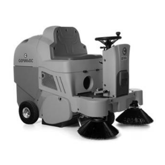
Technical description CS700 and CS800 are ride-on sweeping machines, powered electrically (with traction batteries) or with an internal combustion (endothermic) engine, for the cleaning of both internal and external surfaces with tiled, concrete or asphalt floors. -
Page 6: Symbols Used On The Machine
SYMBOLS USED ON THE MACHINE Main switch symbol (key switch) Used on the instrument panel, to indicate the key switch for machine operation on (I) or off (O) Symbol denoting endothermic engine air Used on the instrument panel, to indicate the knob that controls the activation of the lever for the air of the endothermic engine Debris hopper tipping symbol Is used on the instrument panel to indicate the yellow three-position momentary switch, which controls the rotation of the debris hopper... - Page 7 SYMBOLS USED ON THE MACHINE Central/side brush(es) motion symbol (idle position) Used to indicate the movement linkage of the central/side brush(es) Central/side brush(es) motion symbol (working position) Used to indicate the movement linkage of the central/side brush(es) Symbol for work speed adjustment Used on the steering column, to indicate the manual accelerator Indicates the risk of crushed hands Indicates the risk of burns due to the hot surface...
-
Page 8: General Safety Regulations
GENERAL SAFETY REGULATIONS The regulations below must be carefully followed in order to avoid harm to the operator and damage to the machine. WARNING: • Read the labels on the machine carefully. Do not cover them for any reason and replace them immediately if they become damaged. •... -
Page 9: Machine Preparation
The machine is contained in specific packaging with a pallet for the handling with fork trucks. The packages cannot be placed on top of each other. The total weight of the machine with its packaging is 385kg (for CS700 H versions) The total weight of the machine with its packaging is 470kg (for CS800 H versions) The dimensions of the packaging is as follows: CS700 B –... -
Page 10: How To Move The Machine
MACHINE PREPARATION 3. HOW TO MOVE THE MACHINE Make sure the hopper is empty, otherwise empty it completely Check the central brush is lifted up off the ground Check the side brush(es) is/are lifted up off the ground Place it on a pallet, using a chute Check that the key switch is on OFF and remove the key Engage the parking brake Secure the machine to the pallet using wooden wedges... -
Page 11: Footboard Front-Left Components
MACHINE PREPARATION 7. FOOTBOARD FRONT-LEFT COMPONENTS The components at the front right of the footboard are identified as follows: 14. Service brake pedal 15. Parking brake lever 8. FOOTBOARD REAR COMPONENTS The components at the rear of the footboard are identified as follows: 16. -
Page 12: Maintenance And Disposal Of The Starter Battery
MACHINE PREPARATION 13. MAINTENANCE AND DISPOSAL OF THE STARTER BATTERY For information about battery maintenance, refer to the instructions provided by the battery manufacturer. When the battery reaches the end of its working life, it must be disconnected by expert, trained personnel, then lifted (using the grips and suitable lifting devices) to remove it from the battery compartment. -
Page 13: Side Brush Assembly
MACHINE PREPARATION 5. To access the motor compartment, grip the rear part of the seat casing (3). 6. Rotate and raise the seat casing until the safety lock is engaged. 7. Check the oil is not below the minimum level, as seen on the transparent cap (4). If necessary, add more oil by following the instructions in the “MAINTAINING THE HYDRAULIC OIL LEVEL”... -
Page 14: Blinking Light (Optional)
MACHINE PREPARATION ATTENTION: The mechanical brake pedal does not affect the traction of the machine. Before every operation, check that the parking brake is disengaged (lever 14) and avoid continuous and prolonged use of the mechanical brake pedal (pedal 13), in order to avoid damage to the traction wheel or to the traction motor. -
Page 15: Work
WORK 22. PREPARING TO WORK 1. Check that the debris hopper is empty; if not, empty it completely 2. Check that the parking brake is engaged and, if not, engage it 3. Check the fuel level; if it is low, top up the tank (as indicated in “FILLING THE FUEL TANK”) 4. - Page 16 WORK Lower the central brush by turning the left lever (5) anticlockwise. 10. Lower the right side brush (1SL versions) or both side brushes (2SL versions) by turning the right lever (4) clockwise. ATTENTION: Use the side brush or brushes (according to machine version) only on edges, as it is not assisted by the vacuum action.
-
Page 17: Emptying The Debris Hopper (Manual Movement)
WORK 23. EMPTYING THE DEBRIS HOPPER (MANUAL MOVEMENT) The machine is NOT equipped with a device to warn you when the debris hopper is full, so it is a good idea to empty it frequently while working. In order to empty the debris hopper, proceed as follows: 1. -
Page 18: Emptying The Debris Hopper (Manual Movement)
WORK 24. EMPTYING THE DEBRIS HOPPER (MANUAL MOVEMENT) The machine is NOT equipped with a device to warn you when the debris hopper is full, so it is a good idea to empty it frequently while working. In order to empty the debris hopper, proceed as follows: 1. - Page 19 WORK 18. Move the switches (4) and (5) backward, until the debris hopper has returned to the working position WARNING! If the debris hopper is not in the correct position the machine will not work to its full potential.
-
Page 20: At The End Of The Work
AT THE END OF THE WORK 25. AT THE END OF THE WORK (VERSIONS WITH MANUAL EMPTYING OF THE DEBRIS HOPPER) At the end of the work, and before carrying out any type of maintenance, perform the following operations: 1. Stop the machine and engage the parking brake 2. -
Page 21: At The End Of The Work (Versions With Automatic Emptying Of The Debris Hopper)
AT THE END OF THE WORK 26. AT THE END OF THE WORK (VERSIONS WITH AUTOMATIC EMPTYING OF THE DEBRIS HOPPER) At the end of the work, and before carrying out any type of maintenance, perform the following operations: 1. Stop the machine and engage the parking brake 2. - Page 22 AT THE END OF THE WORK 17. Move the switches (4) and (5) backward, until the debris hopper has returned to the working position WARNING! If the debris hopper is not in the correct position the machine will not work to its full potential.
-
Page 23: Daily Maintenance
DAILY MAINTENANCE PERFORM ALL MAINTENANCE OPERATIONS IN SEQUENCE 27. CLEANING THE CENTRAL BRUSH Proceed as follows in order to clean the central brush: 1. Engage the parking brake. 2. Check the main machine switch is in the “OFF-0” position. If this is not the case, turn the key by a quarter rotation to the left. -
Page 24: Cleaning The Side Brush
DAILY MAINTENANCE 13. Reassemble all the elements. ATTENTION: The brush is correctly fitted when, seen from above, the cusp forms an upturned “V” (refer to the picture) 28. CLEANING THE SIDE BRUSH Proceed as follows in order to clean the side brush: 1. -
Page 25: Weekly Maintenance
WEEKLY MAINTENANCE 29. CLEANING THE PANEL FILTER (FP VERSIONS) Whenever the vacuum action seems to be unsatisfactory, check that the vacuum filter is not obstructed. If necessary clean with an air jet as follows: 1. Engage the parking brake. 2. Check the main machine switch is in the “OFF-0” position. If this is not the case, turn the key by a quarter rotation to the left. -
Page 26: Cleaning The Fabric Filter (Fs Versions)
WEEKLY MAINTENANCE 30. CLEANING THE FABRIC FILTER (FS VERSIONS) Whenever the vacuum action seems to be unsatisfactory, check that the vacuum filter is not obstructed. If necessary clean with an air jet as follows: 1. Engage the parking brake. 2. Check the main machine switch is in the “OFF-0” position. If this is not the case, turn the key by a quarter rotation to the left. -
Page 27: Cleaning The Debris Hopper (Versions With Manual Emptying Of The Debris Hopper)
WEEKLY MAINTENANCE 31. CLEANING THE DEBRIS HOPPER (VERSIONS WITH MANUAL EMPTYING OF THE DEBRIS HOPPER) Clean the debris hopper every week as follows: 1. Engage the parking brake. 2. Check the main machine switch is in the “OFF-0” position. If this is not the case, turn the key by a quarter rotation to the left. -
Page 28: Side Brush Adjustment
WEEKLY MAINTENANCE 11. Move the switch (2) backward, until the debris hopper has returned to the working position 12. Move the switches (2) and (1) backward, until the debris hopper has returned to the working position WARNING! If the debris hopper is not in the correct position the machine will not work to its full potential. -
Page 29: Checking The Motor Oil Level
WEEKLY MAINTENANCE 8. Using a suitable tool, loosen the adjustment screw (6) until the brush bristles are pressed onto the floor by about 2cm. WARNING: This operation must be carried out using gloves to protect against contact with dangerous solutions. 9. -
Page 30: Maintaining The Hydraulic Oil Level
WEEKLY MAINTENANCE WARNING: Check the oil level when the motor is switched off, and with the machine on an even surface. WARNING: Refer to the motor use and maintenance manual (supplied with the machine) to check the most suitable type of oil. 35. -
Page 31: Extraordinary Maintenance
EXTRAORDINARY MAINTENANCE 36. CENTRAL BRUSH REPLACEMENT If the central brush is worn, this will affect its performance. Proceed as follows to replace: 1. Engage the parking brake. 2. Check the main machine switch is in the “OFF-0” position. If this is not the case, turn the key by a quarter rotation to the left. -
Page 32: Side Brush Replacement
EXTRAORDINARY MAINTENANCE 37. SIDE BRUSH REPLACEMENT If the side brush is worn, this will affect its performance. Proceed as follows to replace: 1. Engage the parking brake. 2. Check the main machine switch is in the “OFF-0” position. If this is not the case, turn the key by a quarter rotation to the left. -
Page 33: Troubleshooting
TROUBLESHOOTING 38. THE MACHINE DOES NOT START 1. Check the starter battery is connected to the machine system 2. Check the key switch is ON/I 3. Check the starter battery is charged 4. Check there is fuel in the motor tank 39. - Page 34 TROUBLESHOOTING 7. Rotate the lever (6) on the by-pass valve until it is vertical; this will put the hydraulic system on standby. 8. Lower the seat casing as far as the working position. 9. Take the machine to the designated machine storage place. 10.
-
Page 35: Disposal
DISPOSAL To dispose of the machine, take it to a demolition centre or an authorised collection centre. Before scrapping the machine, it is necessary to remove and separate the following materials and then send them to the appropriate collection centres, in accordance with currently effective environmental hygiene regulations: •... -
Page 36: Choosing And Using The Brushes
1.1 + 0.7 Central brush 435164 PPL + Bronze Central brush, white 435165 PPL + Bronze Central brush, black CS700 H 1SL 435166 PPL + Steel Central brush, black 435433 Side brush, black 435432 PPL + Steel 1.1 + 0.7... -
Page 37: Ec Declaration Of Conformity
The undersigned manufacturer: COMAC S.p.A. Via Maestri del Lavoro, 13 37059 Santa Maria di Zevio (VR) declares under its sole responsibility that the product SWEEPING MACHINES mod. CS700 H comply with the requirements of the following Directives: • 2006/42/EC: Machinery Directive. •... -
Page 38: Ec Declaration Of Conformity
EC DECLARATION OF CONFORMITY The undersigned manufacturer: COMAC S.p.A. Via Maestri del Lavoro, 13 37059 Santa Maria di Zevio (VR) declares under its sole responsibility that the product SWEEPING MACHINES mod. CS800 H comply with the requirements of the following Directives: •... - Page 39 COMAC spa Via Maestri del Lavoro, 13 – 37059 Santa Maria di Zevio – Verona – ITALY Tel. +39 045 8774222 – Fax +39 045 8750303 - E-mail: com@comac.it info@comac.it www.comac.it...
- Page 40 COMAC spa Via Maestri del Lavoro, 13 – 37059 Santa Maria di Zevio – Verona – ITALY Tel. +39 045 8774222 – Fax +39 045 8750303 - E-mail: com@comac.it info@comac.it www.comac.it...
Need help?
Do you have a question about the CS700 and is the answer not in the manual?
Questions and answers