Advertisement
Available languages
Available languages
Do Not use control with DC fans
BE SURE TO FOLLOW ALL STEPS IN THE ORDER GIVEN.
BE SURE POWER IS OFF AT FUSE, OR CIRCUIT BREAKER BOX.
WARNING: To avoid fire, shock and serious personal
injury, follow these instructions:
A. Read your owner's manual carefully, retain owner's
manual for future reference.
B. To avoid possible electrical shock, be sure
electricity is turned off at the fuse box or circuit
breaker panel before wiring.
C. This switch is designed for ceiling fan only, to avoid
overheating and possible damage to other
equipment, do not install to control receptacle,
fluorescent
lighting
appliance, transformer-supplied appliance or near
heat source.
D. All wiring must conform to national and local
electrical codes. If you feel you do not have
enough electrical knowledge, have a licensed
electrician install the control.
E. Total amperage and/ or wattage for your fan should
not exceed 120 Volts, 60 HZ, 1.25A (Max.)
1. Turn power OFF at fuse box or circuit breaker and
remove the existing wall plate and switch, do not
remove wires before noting their position. (Figure 1).
2. Make wire connections (Figure 2) and secure with
wire nuts supplied.
● Connect the black wire from the fan to black wire
from the wall control.
● Connect the blue wire from the fan to the blue wire
from the wall control.
● Connect the white (neutral) wire from the ceiling to
the white wire from the fan.
● Connect the black (hot) wire from the ceiling to the
black/white wire from the wall control.
● If your outlet box has a ground wire (green or bare
copper) connect the wall control's ground wire to
it; otherwise connect the wall control's ground wire
directly to one of the screws from the outlet box.
3. Attach the control to the outlet (wall) box and secure
with 2 outlet box screws (Figure 3).
4. Attach the wall plate over the wall control and secure
with the two screws provided (Figure 3).
For Warranty Information please visit www.hinkley.com
fixture,
motor-operated
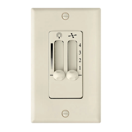
4 SPEED FAN & LIGHT
INSTALLATION INSTRUCTIONS
READ AND SAVE THESE INSTRUCTIONS
Outlet box
Fig. 1
Hot
Black
Black/
White
120 VAC
60Hz
Green/
Ground
Wall control
Neutral
White
Fig. 2
Outlet box
Wall control
Screws
Fig. 3
WALL CONTROL
Model: 980008
Switch
Wall plate
Black
Black
Blue
Blue
White
Fan
Wall plate
Screws
Advertisement
Table of Contents

Related Manuals for Hinkley 980008


Summary of Contents for Hinkley 980008
- Page 1 3. Attach the control to the outlet (wall) box and secure with 2 outlet box screws (Figure 3). 4. Attach the wall plate over the wall control and secure with the two screws provided (Figure 3). For Warranty Information please visit www.hinkley.com Screws Fig. 3 Screws...
- Page 2 INSTRUCCIONES DE INSTALACIÓN DEL VENTILADOR Y DE LA PARED DE 4 VELOCIDADES Modelo: 980008 LEA Y GUARDE ESTAS INSTRUCCIONES No use el control con ventiladores DC ASEGÚRESE DE SEGUIR TODOS LOS PASOS EN LA ORDEN DADA. ASEGÚRESE DE QUE LA ENERGÍA ESTÁ APAGADA EN EL FUSIBLE O EN LA CAJA DE INTERRUPTOR DE CIRCUITO.
- Page 3 INSTRUCTIONS D'INSTALLATION DE LA COMMANDE VENTILATEUR ET COMMANDE MURALE À 4 VITESSES Modèle: 980008 N'utilisez pas la commande avec des LISEZ ET CONSERVEZ CES INSTRUCTIONS ventilateurs CC ASSUREZ-VOUS DE SUIVRE TOUTES LES ÉTAPES DE L'ORDRE DONNÉ. ASSUREZ-VOUS QUE L'ALIMENTATION EST COUPÉE AU FUSIBLE OU AU BOÎTIER DU DISJONCTEUR..
Need help?
Do you have a question about the 980008 and is the answer not in the manual?
Questions and answers