Table of Contents
Advertisement
Quick Links
Advertisement
Table of Contents

Related Manuals for Touch Dynamic Orion

Summary of Contents for Touch Dynamic Orion
- Page 1 User Manual Revision v1.0 December Orion...
- Page 2 Copyright 2009 February All Rights Reserved Manual Version 1.0 Part Number: The information contained in this document is subject to change without notice. We make no warranty of any kind with regard to this material, including, but not limited to, the implied warranties of merchantability and fitness for a particular purpose.
- Page 3 Safety IMPORTANT SAFETY INSTRUCTIONS To disconnect the machine from the electrical power supply, turn off the power switch and remove the power cord plug from the wall socket. The wall socket must be easily accessible and in close proximity to the machine. Read these instructions carefully.
- Page 4 CAUTION ON LITHIUM BATTERIES There is a danger of explosion if the battery is replaced incorrectly. Replace only with the same or equivalent type recommended by the manufacturer. Discard used batteries according to the manufacturer’s instructions. LEGISLATION AND WEEE SYMBOL 2002/96/EC Waste Electrical and Electronic Equipment Directive on the treatment, collection, recycling and disposal of electric and electronic devices and their components.
- Page 5 Revision History Changes to the original user manual are listed below: Version Date Description 2009 December Initial release ...
-
Page 6: Table Of Contents
Table of Content Packing List ........................7 System View .........................8 2.1. Front View......................8 2.2. Rear View ......................9 Peripherals Installation ....................10 3.1. B89 Cash Drawer Installation ................10 3.2. B99 Cash Drawer Installation ................12 System Disassembly ....................14 4.1. Removing the Front Cover.................14 4.2. Removing the Top Cover ...................15 4.3. -
Page 7: Packing List
1. Packing List Take the system unit out of the carton. Remove the unit from the carton by holding it by the foam inserts. The following contents should be found in the carton: a. Driver CD b. Power Cable Note: The power cord type various according to different country and region. -
Page 8: System View
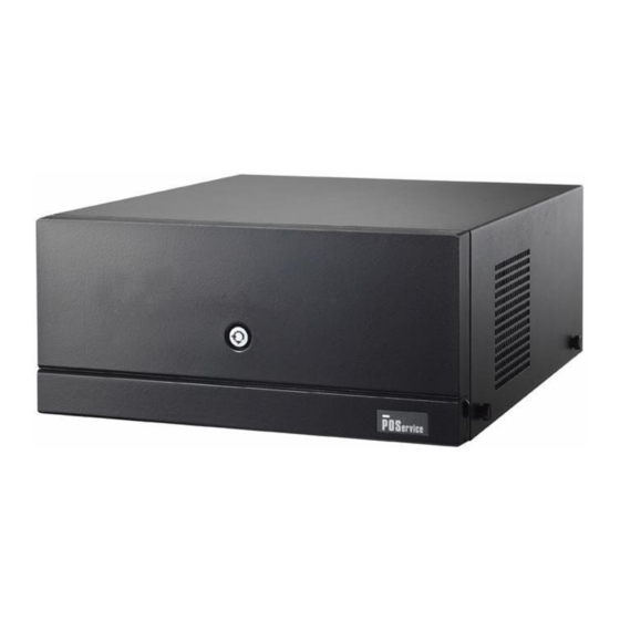
2. System View 2.1. Front View Power Button Key Lock Powe... -
Page 9: Rear View
2.2. Rear View Power Power Power AC Power COM2 & 4 COM 6 Line Out DC Output 24V Cash COM 3 & 5 P/S 2 Drawer Keyboard COM1 DC Output 12V Note: The maximum current that can be drawn from each COM port is 500 mA. DC output 24V Pin Assignment... -
Page 10: Peripherals Installation
3. Peripherals Installation 3.1. B89 Cash Drawer Installation You can install a cash drawer through the cash drawer port. Please verify the pin assignment before installation Cash Drawer Pin Assignment Signal DOUT bit0 DIN bit0 12V / 24V DOUT bit1 Cash Drawer Controller Register The Cash Drawer Controller use one I/O addresses to control the Cash Drawer. - Page 11 Bit 7: Reserved. Bit 6: Reserved. Bit 5: Reserved. Bit 4: Cash Drawer “DIN bit0” pin input status. = 1: the Cash Drawer closed or no Cash Drawer. = 0: the Cash Drawer opened. Bit 3: Reserved. Bit 2: Cash Drawer “DOUT bit0” pin output control. = 1: Opening the Cash Drawer = 0: Allow closing the Cash Drawer Bit 1: Cash Drawer “DOUT bit1”...
-
Page 12: B99 Cash Drawer Installation
3.2. B99 Cash Drawer Installation You can install a cash drawer through the cash drawer port. Please verify the pin assignment before installation. Cash Drawer Pin Assignment Signal DOUT bit0 DIN bit0 12V / 24V DOUT bit1 Cash Drawer Controller Register The Cash Drawer Controller use one I/O addresses to control the Cash Drawer. - Page 13 Bit 7: Reserved Bit 6: Cash Drawer “DIN bit0” pin input status. = 1: the Cash Drawer closed or no Cash Drawer = 0: the Cash Drawer opened Bit 5: Reserved Bit 4: Reserved Bit 3: Cash Drawer “DOUT bit1” pin output control. = 1: Opening the Cash Drawer = 0: Allow close the Cash Drawer Bit 2: Cash Drawer “DOUT bit0”...
-
Page 14: System Disassembly
4. System Disassembly 4.1. Removing the Front Cover a. Use the key to unlock the front cover b. Lift the front cover up in the direction Remove the front cover as shown by the arrows c. Remove the front cover... -
Page 15: Removing The Top Cover
4.2. Removing the Top Cover To remove the top cover, please follow the steps as described in chapter 5.1. a. Remove the screw (1) b. Loosen the thumb screws (4) (two from each side) to release the top cover from the system. 4.3. - Page 16 c. Disconnect the cables (4). d. Use your finger to pull the HDD holder out. e. Remove the HDD. f. Repeat the step d. and e. to remove the other HDD.
-
Page 17: Replacing The Dvd-Rom
4.4. Replacing the DVD-ROM To replace the front cover, please follow the steps as described in chapter 5.1 a. Loosen the thumb screw (1) b. Pull the DVD-ROM holder out c. Disconnect the cables (2) to remove the DVD-ROM... -
Page 18: Replacing The Power Supply
4.5. Replacing the Power Supply To replace the power supply, please follow the steps as described in chapter 5.1 and 5.2 d. Remove the screw (1) and slide the e. Disconnect the cables (3) to release the power supply holder in the direction as power supply holder from the system. -
Page 19: Replacing The I/O & Pci Extension Module
4.6. Replacing the I/O & PCI Extension Module To replace the I/O and PCI extension module, please follow the steps as described in chapter 5.1 and 5.2 a. Remove the extension module by gently b. Disconnect the cables (3) and remove pulling it upwards taking care not to the I/O module from the holder. -
Page 20: Replacing The Memory
4.7. Replacing the Memory To replace the memory, please follow the steps as described in chapter 5.1, 5.2, 5.5(a) a. Use your finger to push the DIMM slot b. Remove the memory module from the ejector clips into the down position. slot. - Page 21 c. Remove the screws (7) d. Remove the hex screws (14) to release the motherboard from the chassis...
-
Page 22: Specification
5. Specification Mainboard Intel SK478 CPU Up to P4 2.6G, Intel P4 / Celeron / Core 2 Duo CPU Support Celeron 2.5G, Mobile Celeron LGA775 1.2G INTEL 945G FSB 533 / 800 / INTEL 852GM + ICH4 Chipset 1066 MHz + ICH7R Up to 4GB DDR ll RAM, Up to 2GB DDR RAM, System Memory... - Page 23 Control / Indicators Power Button 1 (Front) LED_HDD/Power Internal Header 1 ( USB8 ) Power Button 1 ( pin header) Peripherals (special feature) Second HDD (hot swap) 80GB (optional) Supports RAID 0, RAID 1 for RAID 2 SATA HDDs Built-in System ID Option Module ( Connectivity) Powered USB (12V)
-
Page 24: Jumper Settings
6. Jumper Settings 6.1. B89 Jumper Settings B89 Motherboard... - Page 25 B89 Connectors and Jumper Settings ◎ = Factory Default Setting 1. COM1 / COM2 / COM3 / COM4 / COM5 Power Setting COM Port Jumper Pin Function Jumper Setting ◎ -2 COM1 DCD# COM2 COM3 +12V ◎ -8 COM4 COM5 9-10 +12V 11-12...
- Page 26 4. CMOS Operation Mode Setting Function JP13 (SHORT) ◎ COMS Normal COMS Reset 5. Power Mode Setting Function JP15 (SHORT) ◎ ATX Power AT Power 6. Cash Drawer Power Setting Voltage JP7 (SHORT) ◎ -2 +12V + 24V 7. ACPI Mode Setting Function JP12 (SHORT) Disable...
- Page 27 B89 Connector and Pin Definitions CN4: COM6 RS232/422/485 Pin 1 DB9_1 Pin 2 DB9_2 Pin 3 DB9_3 Pin 4 DB9_4 Pin 5 Pin 6 RS232_6_DSR# Pin 7 RS232_6_RTS# Pin 8 RS232_6_CTS# Pin 10 Pin9 RS232_6_RI CN6: Speaker & MIC Connector Pin 1 LIN_OUT_L Pin 2...
- Page 28 CN15: HDD Power Connector Pin 1 +12V Pin 2 Pin 3 Pin 4 CN16: CD-ROM Power Connector Pin 1 +12V Pin 2 Pin 3 Pin 4 CN17: HDD Power Connector Pin 1 +12V Pin 2 Pin 3 Pin 4 CN18: Power Connector external 12V Power connector Pin 1 +12V Pin 2...
-
Page 29: B99 Jumper Settings
6.2. B99 Jumper Settings B99 Motherboard... - Page 30 B99 Connectors and Jumper Settings Connectors Function Connectors Function BAT3 CMOS Battery Base FAN_CPU3 CPU Fan Connector ( use CR2023) LAN & USB5/ USB6 FAN_SYS3 System Fan Connector COM6 Connector IDE3 Primary IDE Connector (40pin pitch = 2.54mm) Speaker & MIC Connector PCI3 PCI Slot CD-in &...
- Page 31 1. COM1 Power Setting ◎Factory Default Setting Function JP4 (SHORT) ◎1-2 DCD# +12V ◎7-8 9-10 +12V 11-12 2. COM 2 Power Setting Function JP8 (SHORT) ◎1-2 DCD# +12V ◎7-8 9-10 +12V 11-12 3. COM 3 Power Setting Function JP6 (SHORT) ◎1-2 DCD# +12V...
- Page 32 5. COM 5 Power Setting Function JP3 (SHORT) ◎1-2 DCD# +12V ◎7-8 9-10 +12V 11-12 6. COM 6 RS232/ 422/ 485 Setting ◎RS232 Function RS422 RS485 JP9 (1-2) JP9 (3-4) JP9 (4-6) JP9 (5-7) JP9 (7-8) JP9 (9-10) JP10 (1-2) JP10 (3-4) JP10 (5-6) JP10 (7-8)
- Page 33 9. Power Mode Setting Function JP14 (SHORT) ◎N/C ATX Power AT Power Cash Drawer Power Setting Voltage JP7 (SHORT) ◎1-2 +12V + 24V 11. System Indicator Function JP15 (SHORT) ◎1-2 3-4 Disable Enable 5-6 7-8 Note: OPEN SHORT...
- Page 34 B99 Connector and Pin Definitions CN4: COM6 RS232 Pin 1 RS485_TXRX- Pin 2 RS485_TXRX+ Pin 3 Pin 4 Pin 5 Pin 6 Pin 7 Pin 8 Pin 9 CN4: COM6 RS485 Pin 1 DCD# Pin 2 Pin 3 Pin 4 DTR# Pin 5 Pin 6...
- Page 35 CN7: USB8 Pin 1 +5V_USB1 Pin 2 USB20_R_P1 Pin 3 USB20_R_P1+ Pin 4 CN8: IrDA Connector Pin 1 Pin 2 IRDA_RX Pin 3 IRDA_TX Pin 4 CN9/10/12/13: Power Connector (+5V/+12V) Pin 1 +12V Pin 2 Pin 3 Pin 4...
-
Page 36: Appendix A: Pci Card Dimension
Appendix A: PCI Card Dimension Maximum dimension of the PCI add-on card: Component Side: 130mm x 90.26mm ( D x W ) (Picture 1) -
Page 37: Appendix B: Drivers Installation
Appendix B: Drivers Installation The shipping package includes a Driver CD in which you can find every individual driver and utility that enables you to install the drivers on the system. Please insert the Driver CD into the drive and double click on the “index.htm” to select the models.
Need help?
Do you have a question about the Orion and is the answer not in the manual?
Questions and answers