Advertisement
Quick Links
Programming the DSP
Introduction
The usual burning (programming) procedure is the 14 steps described on pages 1-5.
Appendix A is required only in case your PC's COM1 is not available for RS232
communication.
Appendix B is required only in case your USB-to-Serial adapter was placed by the
system at COM5 or higher.
Appendix C is required only in case you want to check whether your PC is able to
implement the burning process faster.
Burning Procedure
1. Put the firmware file to be burnt in the proper path:
Recent firmware files are available in IMS site and/or on your CD,
under the folder:
LCIC-WIM - xxx\
LCIC-WIM -
xxx
- Board_Firmware_Update-Up-to-date_Version
(xxx
is the specific type of your board)
For example,
LCIC-WIM - WiM-mode\
LCIC-WIM -
WiM-mode
Copy this folder to your hard disk, let's say under disk C:
C:\
LCIC-WIM - WiM-mode\
LCIC-WIM - WiM-mode - Board_Firmware_Update-Up-to-date_Version
Copy the file to be burnt (for example, LCIC3.121.out) to the folder
"C:\CCStudio_v3.1" and rename it to LCIC.out.
For example:
a. If the file C:\CCStudio_v3.1\LCIC.out' exists, then delete it.
b. Copy the file LCIC_3.121.out
from
C:\
LCIC-WIM - WiM-mode\
LCIC-WIM - WiM-mode - Board_Firmware_Update-Up-to-date_Version
to
C:\CCStudio_v3.1.
c. Rename
C:\CCStudio_v3.1\LCIC_3.121.out
to
C:\CCStudio_v3.1\LCIC.out
C:\CCStudio_v3.1\LCIC.out
24 June 14
- Board_Firmware_Update-Up-to-date_Version
will be the file to be burnt by the SDFlash utility.
1
Advertisement

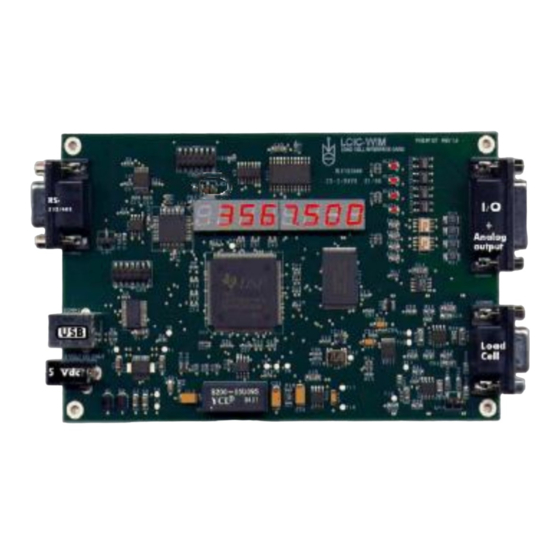
Summary of Contents for IMS LCIC-BAT
- Page 1 Appendix C is required only in case you want to check whether your PC is able to implement the burning process faster. Burning Procedure 1. Put the firmware file to be burnt in the proper path: Recent firmware files are available in IMS site and/or on your CD, under the folder: LCIC-WIM - xxx\ LCIC-WIM -...
- Page 2 2. Unplug card’s power (5V) cord from CONN1: 3. Connect a 3 wire RS232 cable between COM1 of the PC and CONN3 of the LCIC-WIM: * The RS232 cable should be straight (not crossover). * If COM1 is not available, refer to appendix A, below. 4.
- Page 3 5. Re-connect the power (5V) cord to CONN1. Only LED1 (marked below) should light: 6. Double-click the ‘Shortcut to SDFlash.exe’ button on the desktop: (Do not confuse with ‘SdConfig’.)
- Page 4 7. Click ‘File’ and the .sdp file: The following blank layout should appear:...
- Page 5 8. Click ‘Device’ and ‘Flash…’: 9. The following panel should appear: On the bottom panel there should be a message such as: Program C:\CCStudio_v3.1\LCIC.out loaded successfully. Click ‘Start’. 10. The process takes some seconds. Finally the bottom panel should look like this: 11.
-
Page 6: Appendix A: Changing The Port Selection
Appendix A: Changing the PORT Selection When COM1 is not available you may use COM2, COM3 or COM4 instead. If you use a USB-to-Serial adapter and the system automatically placed it at a higher COM location (for example, COM5), refer to appendix B. Click on Project / Settings... -
Page 7: Appendix B: How To Change Com Port Number
Appendix B: How to change COM Port Number Q.: I use a USB-to-Serial adapter in order to communicate with my LCIC-WIM board through its RS232 port. Indeed, the supplied applications such as LCIC-WIM- CALIBRATION work fine. However, when I tried to upgrade board's firmware, I realized that the SDFlash utility supports only COM1 ... - Page 8 3. Locate your COM18 under the 'Ports (COM & LPT)' section: 4. Right-click on COM18 and select 'Properties':...
- Page 9 5. Select the 'Port Settings' tab and click 'Advanced…': 6. Watch the 'COM Port Number':...
- Page 10 7. Replace COM18 by another port between COM1 and COM4. Make sure to select a port which is not reported '(in use)' – in this example we selected COM2: 8. Click 'OK', 'OK'.
- Page 11 9. Right-click on COM2 and select 'Disable': 10. Answer 'Yes' to this question:...
- Page 12 11. Right-click on COM2 and select 'Enable':...
- Page 13 12. Now you should communicate with your board – through the USB-to-Serial adapter – using COM2. First of all, verify proper communication using a known application (such as LCIC-WIM-CALIBRATION). Next, run the SDFlash. Make sure, under 'Project'/'Settings…', in the 'Emulator Address/Id' box, to select C2 (standing for 'COM2'), as described in appendix A: Now you are ready to burn, using the standard burning instructions (the 14 steps described on pages 1 ...
-
Page 14: Appendix C: Changing The Baud Rate Selection
Appendix C: Changing the BAUD RATE Selection Sometimes you may make the burning process faster: Click on Project / Settings... and select the 'Erase' tab: Use 'User Options 3' to set the baud rate. Although this is on the 'Erase' tab, it applies to all operations (Erase, Programming and Verify).
Need help?
Do you have a question about the LCIC-BAT and is the answer not in the manual?
Questions and answers