Table of Contents
Advertisement
Quick Links
Advertisement
Table of Contents

Summary of Contents for Red Digital Cinema RED ROCKET
-
Page 3: Table Of Contents
2.4 Connection Cables ....................2-5 3 SETUP AND OPERATION ............ 3-1 3.1 Firmware Download....................3-1 3.2 Setup of RED Rocket Breakout Box ................. 3-1 3.3 Upgrading Firmware ....................3-2 3.4 Operation of RED Rocket Breakout Box ..............3-3 3.4.1 Turning ON/OFF ................... 3-3 3.4.2 Hot Plugging .................... -
Page 4: Introduction
INTRODUCTION 1.1 OVERVIEW This guide instructs you in the installation and usage of the RED Rocket Breakout Box. The RED Rocket Breakout Box is an accessory for the RED Rocket board. The RED Rocket board is a PCIe-bus single board capable of decoding and debayering REDCODE R3D material in full quality up to 4.5K 12-bit RGB. -
Page 5: Safety Instructions
CAUTION: Please read the following safety instructions very carefully before attempting any instal- lation and/or performing any work on the RED Rocket Breakout Box. If the RED Rocket Breakout Box is not used in compliance with the safety instructions, the warran- ty and all resulting liability claims will be void. -
Page 6: Important Notes
For proper operation and long service life of your RED Rocket Breakout Box, please adhere to these basic environmental condition requirements: DO NOT expose the RED Rocket Breakout Box to sources of heat, such as direct sunlight or a heating source. -
Page 7: Overview
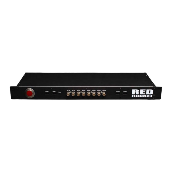
OVERVIEW 2.1 OVERVIEW OF THE FRONT This section provides information detailing the connections located on the front of the RED Rocket Breakout Box. Figure 2-1: RED Rocket Breakout Box - Front MAY 14, 2010 © 2009-2010 RED.COM, INC. - Page 8 HDMI 1 given out via DVI output port A of RED Rocket Breakout Box; additionally, audio channels 1 to 4 will be output Same as HDMI 1 but video signal is same as provided HDMI 2 by DVI output port B of RED Rocket Breakout Box;...
-
Page 9: Overview Of The Rear
2.2 OVERVIEW OF THE REAR This section provides information pertaining to the connection located on the rear of the RED Rocket Breakout Box. Figure 2-2: RED Rocket Breakout Box – Rear Table 2-2: RED Rocket Breakout Box Connector Descriptions - Rear... -
Page 10: Power Led
2.3 POWER LED When power is connected to the RED Rocket Breakout Box, the Power LED provides information about the status of the device (refer to 2.1 OVERVIEW OF THE FRONT): Table 2-3: RED Rocket Breakout Box Power LED Operation... -
Page 11: Connection Cables
DVI 1 Figure 2-3: DMS-59-to-2xDVI-D Cable To fully connect the RED Rocket Breakout Box to the RED Rocket board, two (2) of these cables are required. In environments where quad display applications or similar are not desired, the major connec- tion ’DVI A/B’... -
Page 12: Setup And Operation
3.2 SETUP OF RED ROCKET BREAKOUT BOX To set up the RED Rocket Breakout Box perform the following: 1. Place the RED Rocket Breakout Box on a firm, flat surface or install in a 19" rack-shelf near the computer with the RED Rocket board installed. -
Page 13: Upgrading Firmware
2. Connect the RED Rocket Breakout Box to the DVI A/B and DVI C/D outputs on the RED Rocket board using the DMS-59-to-2×DVI-D connection cables (refer to 2.4 CONNECTION CABLES): Figure 3-1: Connections of the RED Rocket Breakout Box NOTE: In environments where quad display applications or similar are not intended, the major con- nection ’DVI A/B’... -
Page 14: Operation Of Red Rocket Breakout Box
RED Rocket board SDI panel, located on the rear of the RED Rocket board equipped computer, will become inoperative. TURN ON: To turn the RED Rocket Breakout Box on, connect the 5V power adapter to the RED Rocket Breakout Box and plug it into a power outlet. -
Page 15: Aappendix
APPENDIX This chapter provides technical details about the RED Rocket Breakout Box. A.1 TECHNICAL DATA The following shows the technical data for the RED Rocket Breakout Box. Dimensions Height: 44 mm (1.7") Width: 483 mm (19") Depth: 147 mm (chassis, 5.8") 164 mm (max., 6.4") -
Page 16: Conformity Declarations
A.2 CONFORMITY DECLARATIONS The RED Rocket Breakout Box has been tested in accordance with applicable national and international directives and regulations. The following provides further information regarding compliance. A.2.1 RoHS Compliance The EU directive 2002/95/EC ’Restriction of Hazardous Substances (RoHS)’ prohibits the use of certain substances in electrical and electronic equipment. -
Page 17: Fcc Compliance Statement
RED herewith declares that the following equipment has been tested in accordance with the applicable valid FCC regulations: RED Rocket Breakout Box FCC Notice This equipment has been tested and found to comply with the limits for a Class A digital device, pursuant to Part 15 of the FCC Rules.
Need help?
Do you have a question about the RED ROCKET and is the answer not in the manual?
Questions and answers