Advertisement
Tracer
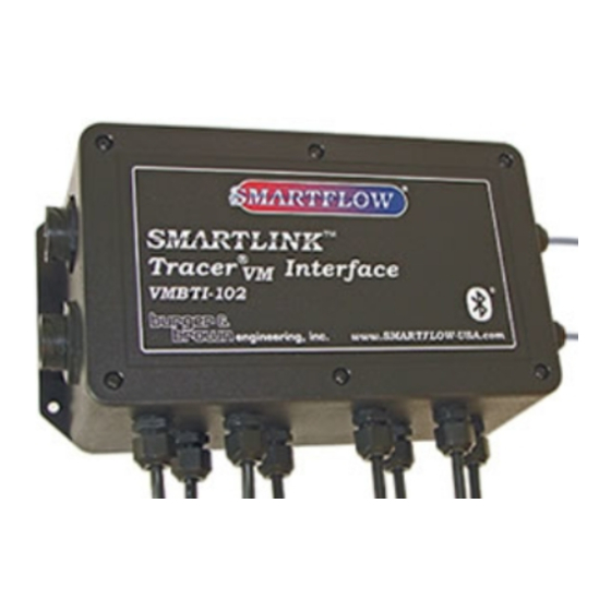
Bluetooth Interface
®
VM
Model number VMBTI-102
Operating Instructions
General
The
Tracer
Bluetooth Interface collects, transmits and saves data from
VM
Tracer
Base Flowmeters installed in injection mold cooling circuits.
VM
Flowmeters purchased separately are connected via cable to the
Bluetooth Interface. The Interface provides power to each flowmeter and
receives voltage signals for temperature and flow.
The
Tracer
Bluetooth Interface wirelessly transmits flow and
VM
temperature for display on a tablet or smartphone. Files can be created
using the free app and saved on USB flash drive connected to the Interface.
The Interface also communicates over Ethernet connection to PC software
for network file storage and alerts. The files are easily read into database
management software for reference or analysis.
When used with PC software, a dry contact switch is available for
connection to a peripheral or machine control to signal an alarm for out of
limit cooling water conditions.
App software is available for download at no cost from Google™ Play or
iTunes™ stores and is required to view data. Search for "Tracervm" to
locate.
PC Based software is provided free of charge from Burger & Brown
Engineering, Inc. It is available for download at this web address: www.
smartflow-usa.com/tracer-vm-bluetooth.htm.
Power
Attach the power cable to the P1 connector according to the chart below.
Individual wires are 24AWG stranded copper. Attach 8 to 28VDC power to
the unit for correct operation. Do not energize the circuit without Tracer
Base units connected.
Power supply other than 8 to 28VDC may damage the
electronics! Ensure that power supply provides Earth Ground
(0V) and not a reference. Earth Ground is required for reliable
flow and temperature output display.
Power Cable Color Chart
Wire Color
Black
Red
Form #206 (10.18)
Function
DC Ground (Earth)
+DC Input (8 to 28VDC)
Tracer
VM
Specifications
Operating Temp. Range .......... 32 to 248°F (0 to 120°C)
Housing ................................................ ABS, NEMA4X
Seals ....................................................................... Buna
Maximum Wireless Range .............................20 meters
Bluetooth Version ...................................... 1.1 4.0+LE 5
Power Required ........... 8 to 28VDC with Earth Ground
Dry Contact Switch Rating .......2A, 250VAC, 220VDC
USB Port Output .................................................. 5VDC
Power Cable ..............2-Conductor, 6 meters (20ft) long
Cord Grips .................... 9 pieces liquid-tight (included)
EMI/RFI Interference
Care should be taken to route power and signal cable
away from motors and pumps. Signal integrity may be
adversely affected by close proximity of the wiring to
machinery producing high frequency emissions.
Cables to Tracer
Maximum effective signal cable length is 2.9m (10ft)
as supplied. Splicing extra length to the cable is not
VM
recommended. Sensor cables are supplied with the
Tracer
Base units.
VM
Flow and Mounting Direction
Orient the Tracer
of the process fluid matches the directional arrow on
the body of each meter. Flow in the opposite direction
of the arrow will yield inaccurate voltage output. The
presence of air bubbles in the process fluid will also
create an inaccurate voltage output. Refer to Tracer
Base Instructions (Form 187) for details.
The Apple logo and iTunes are trademarks of Apple Inc.,
registered in the U.S. and other countries.
Google Play and the Google Play logo are trademarks of
Google Inc.
4500 E 142nd Street • Grandview, MO 64030
Tel. (816) 878-6675 • www.smartflow-usa.com
RoHS Compliant
VM
Base units so the flow direction
VM
VM
Advertisement
Table of Contents

Related Manuals for Smartflow Tracer VMBTI-102

Summary of Contents for Smartflow Tracer VMBTI-102
- Page 1 The Apple logo and iTunes are trademarks of Apple Inc., registered in the U.S. and other countries. Google Play and the Google Play logo are trademarks of Google Inc. 4500 E 142nd Street • Grandview, MO 64030 Tel. (816) 878-6675 • www.smartflow-usa.com Form #206 (10.18)
- Page 2 Cord Grips (9X) 80mm 3.15" Housing Dimensions 3.2mm Figure 1 0.125" Dry Contact Switch Connector Power Connector Indicators Tracer DIP Switches Tracer Cooling Cooling Connectors Circuit Circuit Circuit Board (Cord Grips Bottom) Figure 2 burger & brown engineering, inc. www.smartflow-usa.com...
-
Page 3: Installation
DIP Switch Settings Flow Range Pos. 1 Pos. 2 Pos. 3 1 - 15LPM Future Use 2 - 40LPM Do not adjust. Typical DIP 5 - 100LPM Switch (8X) 10 - 200LPM Figure 6 burger & brown engineering, inc. www.smartflow-usa.com... -
Page 4: App Operation
When running more than one shift, consider using a single tablet instead of individual smartphones to monitor all circuits. • Make sure there is enough storage space on the USB flash drive for your files before starting the logging session. Files generated are usually less than 1MB. burger & brown engineering, inc. www.smartflow-usa.com... -
Page 5: Data Logger Software
• Output File Name (.csv) indicate which Bluetooth Interface is experiencing an alarm. Start the Smartflow Data Logger Application. Check that each Alarm indicators are visible only during a logging session. Tracer Bluetooth Interface is connected to 8 to 28 Volts DC 10. -
Page 6: Troubleshooting
Seller states that the product’s useful safe life is 5 years. Actual life may vary widely depending on operating environment such as temperature, pressure, and chemical exposure. Users are cautioned to refer to instructions for operating limits and a partial list of incompatible chemicals. burger & brown engineering, inc. www.smartflow-usa.com...
Need help?
Do you have a question about the Tracer VMBTI-102 and is the answer not in the manual?
Questions and answers