Table of Contents
Advertisement
Quick Links
High Definition Video Camera
HDC-TM55P
Model No.
HDC-TM55PC
HDC-TM55EB
HDC-TM60P
HDC-TM60PC
HDC-TM60PU
HDC-TM60EB
HDC-TM60EC
HDC-TM60EE
HDC-TM60EF
HDC-TM60EG
HDC-TM60EP
HDC-TM60GC
HDC-TM60GD
HDC-TM60GK
HDC-SD60P
HDC-SD60PC
HDC-SD60PU
HDC-SD60EB
HDC-SD60EC
HDC-SD60EE
HDC-SD60EF
HDC-SD60EG
HDC-SD60EP
© Panasonic Corporation 2010 Unauthorized copy-
ing and distribution is a violation of law.
ORDER NO. VM1002007CE
B27
Advertisement
Table of Contents

Related Manuals for Panasonic HDC-TM55EB


Summary of Contents for Panasonic HDC-TM55EB
- Page 1 HDC-TM55P Model No. HDC-TM55PC HDC-TM55EB HDC-TM60P HDC-TM60PC HDC-TM60PU HDC-TM60EB HDC-TM60EC HDC-TM60EE HDC-TM60EF HDC-TM60EG HDC-TM60EP HDC-TM60GC HDC-TM60GD HDC-TM60GK HDC-SD60P HDC-SD60PC HDC-SD60PU HDC-SD60EB HDC-SD60EC HDC-SD60EE HDC-SD60EF HDC-SD60EG HDC-SD60EP © Panasonic Corporation 2010 Unauthorized copy- ing and distribution is a violation of law.
-
Page 2: Table Of Contents
HDC-SD60GC Vol. 1 Colour HDC-SD60GK [ HDC-TM55 ] HDC-SD60GN (K)...Black Type HDC-SD60GT [ HDC-TM60 ] HDC-SD66EG (S)...Silver Type (only GC) (K)...Black Type (R)...Red Type (only PU/GC/GD/GK) (P)...Pink Type (only GC/GK) (N)...Gold Type (only GC) [ HDC-SD60 ] (S)...Silver Type (except PC/PU/GK/GT) (K)...Black Type (R)...Red Type (except P/PC/PU/EE) (P)...Pink Type (only GC/GK/GT) -
Page 3: Safety Precautions
1 Safety Precautions 1.1. General Guidelines 1.3. Leakage Current Hot Check 1. IMPORTANT SAFETY NOTICE (See Figure 1.) There are special components used in this equipment 1. Plug the AC cord directly into the AC outlet. Do not use which are important for safety. These parts are marked by an isolation transformer for this check. -
Page 4: How To Discharge The Capacitor On Flash P.c
1.4. How to Discharge the Capacitor on Flash P.C.B. • This unit equipped with two pieces of capacitors as flash charging capacitors. “Either one of the capacitor discharging operation” makes discharging for others as well. CAUTION: 1. Be sure to discharge the capacitor on FLASH P.C.B.. 2. -
Page 5: Warning
2 Warning 2.1. Prevention of Electrostatic Discharge (ESD) to Electrostatically Sensitive (ES) Devices Some semiconductor (solid state) devices can be damaged easily by static electricity. Such components commonly are called Elec- trostatically Sensitive (ES) Devices. Examples of typical ES devices are integrated circuits and some field-effect transistors and semiconductor "chip"... -
Page 6: Caution For Ac Cord (For Eb
2.3.2.3. How to Replace the Fuse A replacement fuse cover can be purchased from your local Panasonic Dealer. 1. Remove the Fuse Cover with a screwdriver. If the fitted moulded plug is unsuitable for the socket outlet in your home then the fuse should be removed and the plug cut off and disposed of safety. -
Page 7: How To Replace The Lithium Battery
NOTE: This Lithium battery is a critical component. (Type No.: ML-614S/ZTK Manufactured by Energy Company, Panasonic Corporation) It must never be subjected to excessive heat or discharge. It must therefore only be fitted in requirement designed specifically for its use. -
Page 8: Service Navigation
2. The following category is /are recycle module part. Please send it/them to Central Repair Center. • MAIN P.C.B. (VEP03H84CN: HDC-TM55P/PC, TM60P/PC/PU/GD) • MAIN P.C.B. (VEP03H84CQ: HDC-TM60EE/GC/GK) • MAIN P.C.B. (VEP03H84CP: HDC-TM55EB, TM60EB/EC/EF/EG/EP) • MAIN P.C.B. (VEP03H84DN: HDC-SD60P/PC/PU/GT) • MAIN P.C.B. (VEP03H84DP: HDC-SD60EB/EC/EF/EG/EP, SD66EG) -
Page 9: How To Define The Model Suffix (Ntsc Or Pal Model)
How to Define the Model Suffix (NTSC or PAL model) There are eight kinds of HDC-TM55/TM60/SD60/SD66. • a) HDC-TM55P, TM60P, SD60P • b) HDC-TM55PC, TM60PC, SD60PC • c) HDC-TM55EB, TM60EB/EC/EF/EP, SD60EB/EC/EF/EG/EP/GN, SD66EG • d) HDC-TM60EE, SD60EE • e) HDC-TM60GT • f) HDC-TM60GK, SD60GK •... -
Page 10: Formatting
3.5. Formatting... -
Page 11: Specifications
4 Specifications... -
Page 14: Location Of Controls And Components
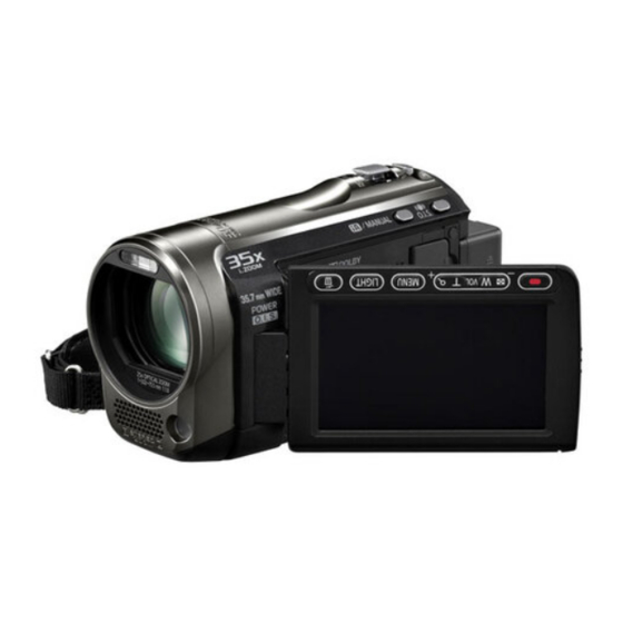
5 Location of Controls and Components Power button [ 1 2 3 4 Speaker Intelligent auto/Manual button [iA/MANUAL] Optical image stabilizer button /O.I.S.] Mode switch Battery holder HDMI mini connector [HDMI] USB terminal [ AV multi connector [AV MULTI] AV MULTI Use the AV multi cable (only the supplied cable). - Page 15 25 Tripod receptacle 26 Battery release lever [BATTERY] 27 Status indicator 28 Photoshot button [ 29 Zoom lever [W/T] (In Motion Picture Recording Mode or Still Picture Recording Mode) Thumbnail display switch [ Volume lever [ VOL ] (In Playback Mode) 30 DC input terminal Do not use any other AC adaptors except...
- Page 16 Selecting a mode Change the mode to recording or playback. Operate the mode switch to change the mode to Motion Picture Recording Mode Still Picture Recording Mode Playback Mode How to use the touch screen You can operate by directly touching the ■...
-
Page 17: Service Mode
6 Service Mode 1. Indication method of the service menu Set the mode switch “Motion Picture Recording” mode. 2. Turn the power on, and then while keep pressing the “Zoom lever” to W side, “Intelligent auto/Manual” button and “Menu” but- ton for more than 3 seconds until the top screen of the Service Mode Menu being displayed. -
Page 18: Built-In Memory Self Check Execution
6.1. Built-in Memory Self Check Execution (HDC-TM55/TM60 only) Touch the [ 3 ] of LCD, select Built-in memory self check execution. Operation specifications Indication contents • Built-in memory self check result display Display the Built-in memory self check result information. Displays other than “OK”... -
Page 19: Power On Self Check Result Display
6.3. Power ON Self Check Result Display Touch the [ 5 ] of LCD, select Power ON self check result display. Operation specifications Indication contents • Power ON self check result display Function to diagnose correct function of the device and interface between devices result display. Display the following commnucation test result. -
Page 20: Service Fixture & Tools
7 Service Fixture & Tools 7.1. When Replacing the Main P.C.B. After replacing the MAIN P.C.B., be sure to achieve adjustment. The adjustment instruction is available at “software download” on the “Support Information from NWBG/VDBG-AVC” web-site in “TSN system”, together with Maintenance software. 7.2. -
Page 21: Disassembly And Assembly Instructions
8 Disassembly and Assembly Instructions 8.1. Disassembly Flow Chart This is a disassembling chart. When assembling, perform this chart conversely. 8.2. PCB Location... -
Page 22: Disassembly Procedure
8.3. Disassembly Procedure Item Removal Side (R) OP P.C.B. Fig.D19 2 Screws (U) Item Removal Unit 1 Screw (V) R Cover Unit Fig.D1 2 Screws (A) Speaker P6501 (Connector) 1 Screw (B) SP Angle Fig.D2 3 Locking tabs Side (R) OP P.C.B. Unit R Cover Unit Speaker Side Case (L) Unit... - Page 23 Item Removal Body Unit Fig.D35 3 Screws (j) Body Unit Zoom Guide Pole Fig.D36 2 Zoom Guide Poles OIS Unit OIS Unit 4th Lens Frame Move Fig.D37 4th Lens Frame Move Unit Unit 2 Focus Guide Poles L Focus Guide Pole L Fig.D2 8.3.2.
- Page 24 8.3.4. Removal of the Top Case Fig.D4 8.3.3. Removal of the ESD P.C.B. Unit Fig.D6 Fig.D5...
- Page 25 8.3.5. Removal of the Lens Frame (L) Unit Fig.D9 Fig.D7 8.3.6. Removal of the Front Case Unit Fig.D10 Fig.D8...
- Page 26 8.3.7. Removal of the Side Case (R) Unit 8.3.8. Removal of the Switch Unit (Top)/ Batt Case Unit Fig.D12 8.3.9. Removal of the SD Frame Fig.D13 Fig.D11...
- Page 27 8.3.10. Removal of the Lens Unit 8.3.11. Removal of the Main P.C.B. Unit Fig.D15 8.3.12. Removal of the Flash P.C.B. Unit Fig.D16 Fig.D14...
- Page 28 8.3.14. Removal of the Side (R) OP P.C.B. Unit and Speaker Fig.D17 8.3.13. Removal of the Switch Unit (Top) and Power FPC Unit Fig.D19 Fig.D18...
- Page 29 8.3.15. Removal of the LCD Case Unit 8.3.16. Removal of the Monitor P.C.B. Unit Fig.D21 Fig.D20...
- Page 30 Fig.D22 Fig.D23...
- Page 31 8.3.17. Removal of the Barrier Motor 8.3.18. Removal of the Front P.C.B. Unit Fig.D25 8.3.19. Removal of the Lens Damper, Bar- rier Lever and Barrier Change Lever Fig.D26 Fig.D24...
- Page 32 8.3.20. Removal of the ECM FPC Unit 8.3.21. Removal of the MOS Unit and IR Fil- Fig.D28 8.3.22. Removal of the IRIS Unit Fig.D27 Fig.D29...
- Page 33 8.3.24. Removal of the Zoom Motor Fig.D30 8.3.23. Removal of the Focus Motor Fig.D32 Fig.D31...
- Page 34 8.3.25. Removal of the 1st Lens Frame Unit 8.3.26. Removal of the 2nd Lens Frame and Reinforcement Plate Move Unit Fig.D34 8.3.27. Removal of the Body Unit Fig.D33 Fig.D35...
- Page 35 8.3.28. Removal of the Zoom Guide Pole and OIS Unit Fig.D36 8.3.29. Removal of the 4th Lens Frame Move Unit and Focus Guide Pole L Fig.D37...
-
Page 36: Measurements And Adjustments
9 Measurements and Adjustments 9.1. Electric Adjustment • Adjustment method is different from a conventional High definition video camera. • An exclusive jig and PC (including software for adjustment “Tatsujin”) are necessary for electric adjustment. • A USB driver for service is necessary to communication with PC. •... - Page 37 Adjustment Items • Adjustment item as follows. The adjustment instruction is available at "Software download" on the "Support Information from NWBG/VDBG-AVC" web-site in "TSN System".
-
Page 38: Factory Setting
10 Factory Setting 10.1. How To Turn On The Factory Settings? 1. Set the mode switch “Motion Picture Recording” mode. 2. Turn the power on, and then while keep pressing the “Zoom lever” to W side, “Intelligent auto/Manual” button and “Menu” but- ton for more than 3 seconds until the top screen of the Service Mode Menu being displayed. -
Page 39: What Is The Factory Settings
10.2. What Is The Factory Settings? The factory settings clean up and/or refresh the following settings. 1. MENU, MODE, ADJUSTMENT VALUE. 2. SD card format. 3. Reset the folder number and file number of still pictures. (Setting the folder number is 100, and file number is 0.) 4. - Page 40 HDC-SD60P HDC-SD60EG it may be differ from actual measurement due to modification of circuit and so on. HDC-TM55PC HDC-TM60EF HDC-SD60PC HDC-SD60EP HDC-TM55EB HDC-TM60EG HDC-SD60PU HDC-SD60GC 5.The voltage being indicated here may be include observational-error (deviation) due to HDC-TM60P HDC-TM60EP HDC-SD60EB HDC-SD60GK internal-resistance and/or reactance of equipment.
-
Page 41: S2. Voltage Chart
S2. Voltage Chart Note) Indicated voltage values are the standard values for the unit measured by the DC electronic circuit tester (high-impedance) with the chassis taken as standard. Therefore, there may exist some errors in the voltage values, depending on the internal impedance of the DC circuit tester. S2.1. -
Page 42: S3. Block Diagram
S3. Block Diagram S3.1. Overall Block Diagram NOTE : VIDEO SIGNAL : AUDIO SIGNAL : CLK or CONTROL LINE LENS(F1.8-3.3 25x) IC201 ZOOM/ MOS IMAGE FOCUS IRIS/ SENSOR MOTOR/ Analog COLOR LCD PANEL X301 (42.725275MHz) IC701 Analog LENS/OIS DRIVE MULTI Analog TERMINAL Analog... -
Page 43: S4. Schematic Diagram
S4. Schematic Diagram S4.1. Interconnection Diagram HDC-TM55/TM60 only ESD P.C.B. ECM FPC FRONT P.C.B. (FOIL SIDE) MOS UINT LENS UNIT FP6600 ESD FPC MOS FPC LENS SD HOLDER P.C.B. BARRIER (FOIL SIDE) PS6002 PP6401 SD CLK NOREG GND TRACEPKT7 UARTO SD GND NOREG GND TRACEPKT6... -
Page 44: S4.2. Strobe Schematic Diagram
S4.2. Strobe Schematic Diagram TO FRONT FP7001 K1MY16BA0159 TO MAIN Q4801 B1ABDF000017 PS7001 G_ECML K1KB30AA0116 C3301 MIC_GND R4817 R4816 MIC_GND 4700 G_ECMR D_GND LENSBA_MT_B+ LENSBA_MT_B+ D_GND LENSBA_MT_A+ S_HDD_G_SDA LENSBA_MT_A+ S_HDD_G_SDA LENSBA_MT_B- S_HDD_G_SCL LENSBA_MT_B- S_HDD_G_SCL F3E0J106A009 LENSBA_MT_A- CHARGE CHARGE LENSBA_MT_A- R4818 C4817 OP_LED CHAEND... -
Page 45: S4.3. Front Schematic Diagram
S4.3. Front Schematic Diagram LED_LIGHT LIGHT_ON_H TO_ECM R6605 R6606 FP6601 4300 68K[D] K1MN04BA0197 (2SA2174J0L) (2SC6054J0L) B1ADCF000161 B1ABDF000017 Q6623 ECM[R] Q6622 GND[R] GND[L] R6603 ECM[L] R6607 18K[D] R6604 R6608 C6604 TO_STROBE_PCB 3300[D] K1MN16BA0197 16V0.1[15] FP6603 G_ECML MIC_GND MIC_GND TO LENSBARRIER G_ECMR LENSBA_MT_B+ FP6600 LENSBA_MT_B+... -
Page 46: S4.4. Sd Schematic Diagram
S4.4. SD Schematic Diagram G_SENSOR/TEMP_SENSOR PP6401 K1KA40BA0052 CLK49_SDCA_A SD CLK SD_GND BUS24_SDTA1 SD DATA1 R3907 E_CARD_PRO_A BUS24_SDTA0 SD DATA0 R3909 E_CARD_DET_A BUS24_SDTA3 SD DATA3 BUS24_SDTA2 SD DATA2 R3906 SD_GND CLK49_SDCA_A CLK24_SDCMDA SD CMD SD_GND PW_GYRO3V PW_GYRO3V GYRO_GND R3908 PW_SD3R2V $[18] PW_SD3R2V PW_SD3R2V_1 PW_SD3R2V... -
Page 47: S4.5. Side R Schematic Diagram
S4.5. Side R Schematic Diagram TO MAIN TO SPEAKER K1MY06BA0370 FP6501 P6501 K1KY02A00010 SPOUT2 SPOUT2 SPOUT2 SPOUT2 SPOUT1 SPOUT1 SPOUT1 SPOUT1 POWER_SW POWER_SW D_GND POWER ON/OFF S6501 K0F111A00589 HDC-TM60/TM55/SD60/SD66 Side R Schematic Diagram... -
Page 48: S4.6. Monitor Schematic Diagram
S4.6. Monitor Schematic Diagram TO MAIN TO LCD PANEL FP901 FP904 K1MY16BA0159 K1MY41BA0369 [0.5mm][SHITA] [0.3mm][SHITA][t=0.2mm] CLK18_LCD VGL2 CLK18_LCD PW_REG1R8V PW_REG1R8V PW_REG3V BUS9_LCDYC0 BUS9_LCDYC0 VCC1 C902 C905 BUS9_LCDYC1 BUS9_LCDYC1 $[18] C906 10V1[18] BUS9_LCDYC2 6.3V BUS9_LCDYC2 VCOMH C903 C907 BUS9_LCDYC3 VCOML BUS9_LCDYC3 BUS9_LCDYC4 6.3V BUS9_LCDYC4... -
Page 49: S4.7. Power Fpc Schematic Diagram
S4.7. Power FPC Schematic Diagram TO MAIN PS6701 K1KB34A00035 L:0.2 S:0.1 POWER_LED L:0.2 S:0.1 STANDBY_LED L:0.2 S:0.1 E_KEYIN1 L:0.6 S:0.1 E_KEYIN4 BATT_+ BATT_+ BATT_+ BATT_+ BATT_+ BATT_- BATT_- BATT_- BATT_- BATT_- BATT_- BATT_- BATT_- BATT_- JK6701 BATT_- K4ZZ04000056 L:4.2 S:0.1 PW_+B BATT_- L:0.15... -
Page 50: S5. Print Circuit Board
S5. Print Circuit Board S5.1. Strobe P.C.B. FP7001 CL7001 CL7002 C4898 T7001 RL7001 C4804 R4809 R4801 L7001 C7001 CH7003 C7050 IC4801 TL7001 C4809 C4817 TL7002 RL7002 C4816 (Component Side) (Foil Side) HDC-TM60/TM55/SD60/SD66 Strobe P.C.B. S-11... -
Page 51: S5.2. Front P.c.b
S5.2. Front P.C.B. R6605 VA6601 R6606 R6608 (Component Side) MK4 MK3 R 6 6 0 4 F P 6 6 0 3 F P 6 6 0 1 (Foil Side) HDC-TM60/TM55/SD60/SD66 Front P.C.B. S-12... -
Page 52: S5.3. Sd P.c.b
S5.3. SD P.C.B. / S5.4. Side R P.C.B. MK4 MK3 MK7 MK8 (Component Side) C3906 Q3901 R3906 R3911 C3911C3950 L6405 RX3901 P 6 5 0 1 (Component Side) (Foil Side) (Foil Side) HDC-TM60/TM55/SD60/SD66 HDC-TM60/TM55/SD60/SD66 SD P.C.B. Side R P.C.B. S-13... -
Page 53: S5.5. Monitor P.c.b
S5.5. Monitor P.C.B. S5.5.1. Monitor P.C.B. (Component Side) (Component Side) HDC-TM60/TM55/SD60/SD66 Monitor P.C.B. (Component Side) S-14... -
Page 54: S5.5.2. Monitor P.c.b. (Foil Side
S5.5.2. Monitor P.C.B. (Foil Side) C905 C907 CH904 CH905 CH906 C908 C909 CH907 C910 C916 C917 C918 C504 C505 (Foil Side) HDC-TM60/TM55/SD60/SD66 Monitor P.C.B. (Foil Side) S-15... -
Page 55: S5.6. Power Fpc P.c.b
S5.6. Power FPC P.C.B. JK6701 RL6702 RL6701 VA6701 C6701 FP6701 PS6701 (Component Side) (Foil Side) HDC-TM60/TM55/SD60/SD66 Power FPC P.C.B. S-16... -
Page 56: S6. Replacement Parts List
S6. Replacement Parts List Note: 1.* Be sure to make your orders of replacement parts according to this list. 2. IMPORTANT SAFETY NOTICE Components identified with the mark have the special characteristics for safety. When replacing any of these components, use only the same type. 3. - Page 57 HDC-SD60EG-K vol.1 Ref.No. Part No. Part Name & Description Remarks Ref.No. Part No. Part Name & Description Remarks VEP03H84DP MAIN PCB UNIT 1 SD60EG,EP,EF,EB,EC, SD66EG (RTL) E.S.D. VEP03H84DQ MAIN PCB UNIT 1 SD60EE,GC,GK,GN VEP20C81A FRONT PCB UNIT (RTL) E.S.D. (RTL) E.S.D. VEP03H84DN MAIN PCB UNIT 1 SD60P,PC,PU,GT...
- Page 58 HDC-SD60EG-K vol.1 Ref.No. Part No. Part Name & Description Remarks Ref.No. Part No. Part Name & Description Remarks R3913 D0GB150JA057 M.RESISTOR CH 1/10W 15 R3914 ERJ2GEJ103 M.RESISTOR CH 1/10W 10K VEP06G49A SIDE R OP PCB UNIT (RTL) E.S.D. R6405 ERJ6GEYJ222V M.RESISTOR CH 1/8W 2.2K R6451 ERJ2GEJ821 M.RESISTOR CH 1/10W 820...
- Page 59 HDC-SD60EG-K vol.1 Ref.No. Part No. Part Name & DescriptionPcs Remarks Ref.No. Part No. Part Name & DescriptionPcs Remarks VYK3V24 FRONT CASE UNIT 1 (-K,-H) VYK3Q92 FRONT CASE UNIT 1 (-S,-R,-P,-N) VEP04954A ECM FPC UNIT VMG1927 LENS DAMPER VGQ0K82 BARRIER LEVER VGQ0K83 BARRIER CHANGE LEVER VGQ0K84...
- Page 60 HDC-SD60EG-K vol.1 Ref.No. Part No. Part Name & DescriptionPcs Remarks Ref.No. Part No. Part Name & DescriptionPcs Remarks VEP03H84DP MAIN PCB UNIT 1 SD60EG,EP,EF,EB,EC, SD66EG (RTL) E.S.D. VEP03H84DQ MAIN PCB UNIT 1 SD60EE,GC,GK,GN (RTL) E.S.D. VEP03H84DN MAIN PCB UNIT 1 SD60P,PC,PU,GT (RTL) E.S.D.
- Page 61 HDC-SD60EG-K vol.1 Ref.No. Part No. Part Name & Description Remarks Ref.No. Part No. Part Name & Description Remarks VYK3V36 LCD CASE (T) UNIT 1 (-K)SD60EG,EP,EF,EB,EC, EE,P,PC,PU,GC,GT,GK,GN VYK3R00 LCD CASE (T) UNIT 1 (-S)SD60EG,EP,EF,EB,EC, EE,P,GC,GN VYK3V39 LCD CASE (T) UNIT 1 (-R)SD60EG,EP,EF,EB,EC, GC,GT,GK,GN VYK3X27 LCD CASE (T) UNIT...
- Page 62 HDC-SD60EG-K vol.1 Ref.No. Part No. Part Name & Description Remarks Ref.No. Part No. Part Name & Description Remarks VXQ1848 MOS UNIT VXW1109 LENS UNIT VXQ1849 1ST LENS FRAME UNIT VMB4361 1ST LENS FRAME SPRING VMB4361 1ST LENS FRAME SPRING VXP3387 2ND LENS FRAME MOVE UNIT VDW1986 BODY UNIT...
- Page 63 HDC-SD60EG-K vol.1 Ref.No. Part No. Part Name & Description Remarks Ref.No. Part No. Part Name & Description Remarks VYQ5232 PACKING CASE UNIT 1 SD60GKK K1HY12YY0004 AV MULTI CABLE VYQ5237 PACKING CASE UNIT 1 SD60GKR K1HY04YY0032 USB CABLE VYQ5239 PACKING CASE UNIT 1 SD60GKP K2CA2CA00025 AC CABLE 1 SD60P,PC,PU, TM60P,PC,PU,...
-
Page 64: S7. Exploded View
S7. Exploded View S7.1. Frame and Casing Section (1) [When FRONT CASE UNIT are exchanged] ECM FPC UNIT(Ref. 32) is not included in FRONT CASE UNIT(Ref. 31). Please detach ECM FPC UNIT from FRONT CASE UNIT for the repair, and install it when you exchange the FRONT CASE UNIT(New parts). S-25... -
Page 65: S7.2. Frame And Casing Section (2
S7.2. Frame and Casing Section (2) S-26... -
Page 66: S7.3. Lcd Section
S7.3. LCD Section S-27... -
Page 67: S7.4. Camera Lens Section
S7.4. Camera Lens Section B213 B214 B215 B210 B211 B209 B201 B212 B208 B202 B206 B203 B205 B204 B216 B217 B207 S-28... -
Page 68: S7.5. Packing Parts And Accessories Section
S7.5. Packing Parts and Accessories Section (HDC-SD60GN) HDC-SD60EB/GC HDC-TM60EB/GC HDC-TM55EB HDC-SD60EG/EP/EF/EC/EE/GC HDC-SD66EG (HDC-TM60GD) HDC-TM60EG/EP/EF/EC/EE/GC HDC-SD60P/PC/PU HDC-TM60P/PC/PU HDC-SD60GK HDC-TM55P/PC (HDC-SD60GT) HDC-TM60GK S-29...
Need help?
Do you have a question about the HDC-TM55EB and is the answer not in the manual?
Questions and answers