
Subscribe to Our Youtube Channel
Summary of Contents for AWT PIM-P
- Page 1 Passive Inter-Modulation Distortion PIM-P Analyzer User’s Manual AWT-Global, LLC. - www.awt-global.com - +1.973.321.3423...
-
Page 2: Table Of Contents
INTRODUCTION ....................... 1-1 SAFETY SUMMARY ......................2-1 SYMBOLS ........................2-2 DISCLAIMER ......................2-3 POWER REQUIREMENTS ..................2-4 PIM-P SERIES PACKING LIST ................2-4 PIM-P ELEMENTS ......................3-1 PIM-P FRONT PANEL ....................3-2 PRECAUTIONS ......................... 4-1 USING HIGH PERFORMANCE RF ACCESSORIES ..........4-5 USING HIGH PERFORMANCE RF CABLES ............ - Page 3 Manufacturing & Design ................10-2 10.1.2 Mechanical ....................10-2 10.1.3 Environment ....................10-2 10.2 How to test PIM ......................10-3 PIM-P Technical Information ..................... 11-1 11.1 Tester Types ........................ 11-2 11.2 Specifications (Data Sheet) ..................11-3 11.2.1 Transmitter Specification ................11-3 11.2.2 Receiver Specifications ................
-
Page 4: Introduction
PIM-P Analyzer User’s Manual INTRODUCTION Copyright AWT-Global, LLC. All rights reserved. - Page 5 PIM-P Analyzer User’s Manual Thank you for choosing an AWT Analyzer. The PIM-P is a high performance instrument that allows users to make reliably, highly accurate measurements of passive intermodulation, in systems and/or components. Our test systems are built to the highest quality standards.
-
Page 6: Safety Summary
PIM-P Analyzer User’s Manual SAFETY SUMMARY Copyright AWT-Global, LLC. All rights reserved. -
Page 7: Symbols
AWT PIM-P Passive Intermodulation Analyzer. Failure to comply with these precautions or with specific warnings elsewhere in this manual violates safety standards of design, manufacture, and intended use of the instrument. AWT assumes no liability for the customer’s failure to comply with these requirements. -
Page 8: Disclaimer
AWT Service center. 2.2 DISCLAIMER PIM-P Analyzers transmit two settable CW RF signals, with a power of up to 25W each, to measure passive intermodulation of components and transmitting systems. ACEWAVETECH is under no circumstances accountable for use of PIM-P analyzer not conforming to laws and regulations of national and local authorities. -
Page 9: Power Requirements
• Low PIM Cable 1m (3.3ft) • Low PIM Load 50W • Install CD & manual * PIM-P and accessories are available in customized versions / packages. Please refer to Appendix A for specific package lists. Copyright AWT-Global, LLC. All rights reserved. -
Page 10: Pim-P Elements
PIM-P Analyzer User’s Manual PIM-P ELEMENTS Copyright AWT-Global, LLC. All rights reserved. -
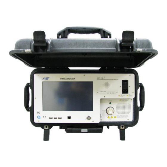
Page 11: Pim-P Front Panel
Element Description Touch screen display 800x600. Never use sharp devices to push Touch Screen Display buttons on the screen Provides information about PIM-P Tx/Rx frequency bands Type Label Loudspeaker for audio signals Audio Main Power Switch PIM-P contains protection circuitry to control RF Power during operation and during powering on/off cycles. - Page 12 PIM-P Analyzer User’s Manual Function similar to a PC: one short push – PIM-P powers up, Another short push – controlled power down Holding it for 3 second – powers unit down Power Switch immediately See also chapter Powering PIM-P up/down.
-
Page 13: Precautions
PIM-P Analyzer User’s Manual PRECAUTIONS Copyright AWT-Global, LLC. All rights reserved. - Page 14 Caution DO NOT operate the PIM-P in any active systems. The PIM-P is a very sensitive Test System that allows testing and analyzing passive RF components. Under no circumstances should the tester be operated when the RF path is active, no outside carrier signals should be present in the RF path under test.
- Page 15 Caution DO NOT block air vents. Due to its high RF output power, PIM-P consumes up to 750W. This energy has to be disposed. While these test systems have protection against overheating, it is vital to keep air vents clear of any obstructions that would prevent or limit the air flow.
- Page 16 Caution Do NOT touch the cable during the measurement Should not touch DUT and the cable which is connected to PIM-P unit after RF Power ON. Touching the cable and DUT makes the contact (the discontinuous contact point) between the unit and them incomplete.
-
Page 17: Using High Performance Rf Accessories
PIM test sets combine very high output power, with extremely sensitive receivers. Note: The sensitivity of the PIM-P receiver is many times greater than the sensitivity of a Base Station. Any unwanted influence generated by poor performing accessories will reduce the accuracy of the desired measurement. - Page 18 Check chapter on Accessories for ordering information of spare and replacement accessories. Accessories are key to accurate PIM measurements. Although properly functioning, they are also wear and tear items and will need to be replaced. Copyright AWT-Global, LLC. All rights reserved.
-
Page 19: Using High Performance Rf Cables
PIM-P cable delivered by AWT is 20cm / 8 inches. To prevent damage, coil cable no tighter than 40 cm / 16 inches in diameter. A transit case for PIM-P systems is available. This case has dedicated space for test systems, accessories and also the low PIM cable. -
Page 20: Powering Pim-P Up/Down
PIM-P Analyzer User’s Manual POWERING PIM-P UP/DOWN Copyright AWT-Global, LLC. All rights reserved. -
Page 21: Powering Up
PIM-P Analyzer User’s Manual 5.1 Powering UP PIM-P Analyzers power up in a similar fashion to a desktop PC. However, there is one exception: significant RF power has to be controlled and managed. For this reason PIM-P series test systems contain a protection system to protect the hardware, e.g. prevents unusual on/and off cycles (e.g. -
Page 22: Powering Down
PIM-P Analyzer User’s Manual 5.2 POWERING DOWN PIM-P can be powered down in different ways listed below. It is not recommended to power down simply by “Pulling the plug” or switching off the Main Switch on the front panel. Exiting The proper way is to Exit the UI is by pressing the red exit button. -
Page 23: Getting Started
PIM-P Analyzer User’s Manual GETTING STARTED Copyright AWT-Global, LLC. All rights reserved. -
Page 24: The First Measurement
PIM-P Analyzer User’s Manual Before starting to measure components with PIM-P systems, users are urged to familiarize themselves with the precautions (Don’ts) in the chapter below. Improper operation and handling can cause bodily harm or damage the instrument. 6.1 THE FIRST MEASUREMENT Preparations: ... - Page 25 Green return button we come back to the Field Mode screen. PIM-P Analyzers provide not only accurate PIM analysis, they also allow users to log data that is specific to a particular test setup or particular base station site. At a later point, measurements can be recalled for comparison and to analyze if the performance has changed.
- Page 26 RF button stops measurements and transmission of RF signal carriers. The last PIM reading is held and shown in grey. Note: PIM-P Analyzers switch RF Power off after 30mins (default). Other cycles or “Always On” can be selected. For more information refer to chapter System Menu.
-
Page 27: Pim-P Operation
PIM-P Analyzer User’s Manual PIM-P OPERATION Copyright AWT-Global, LLC. All rights reserved. - Page 28 For preventive maintenance it can be very helpful to compare actual with historical data, which the PIM-P offers this as well. Measurements can be stored in the system as .log files. Whenever data are logged, the log field stores measurements, test system settings, and even complete information of the base station.
- Page 29 If more detailed information about the DUT is required, it can be accessed by using the Analyzer Mode of the PIM-P Analyzer. In this mode the user can analyze multiple intermodulation products at the same time (Frequency Mode), can record graphical traces over a longer time period (Time Mode) and can frequency sweep DUTs (Sweep Mode) to ensure it performs within the complete frequency band within specification.
-
Page 30: Operations Menu Tree
PIM-P Analyzer User’s Manual 7.1 Operations Menu Tree PIM-P Analyzers are designed to provide an efficient workflow. The Menu Tree shows the overall menu structure of the PIM-P. Copyright AWT-Global, LLC. All rights reserved. -
Page 31: Field Mode
See also chapter Pull-down Menus. Shows Frequency (MHz) and Power level (dBm) of first Carrier Field:F1 carrier signal. Pull down Menu, choices: “Self-Test”, tests PIM-P functionality with RF ON and OFF. System management See also chapter Pull-down Menus. Pull down Menu, choices: Help “Program Information”, shows version of S/W... - Page 32 Opens Carrier Select screen. Carrier For more information see chapter Carrier Select: Active only when RF-Power is OFF. Opens Site Select screen. Site For more information see chapter Site Carrier: Active only when RF-Power is OFF. Copyright AWT-Global, LLC. All rights reserved.
-
Page 33: Carrier Entry
For more information on this see chapter “History Screen”. Carrier Select Once carriers have been stored in the system, they can be easily recalled. The screenshot shows a list of 2 carriers with related information on transmit frequencies and power levels. Copyright AWT-Global, LLC. All rights reserved. - Page 34 Enter button (I) When entering new carrier information, the cursor is set to Carrier Name this field and marked orange for editing. The name will be stored by pushing “Enter” (I) Copyright AWT-Global, LLC. All rights reserved.
- Page 35 “System Menu”. Returns to previous site. Return Automatically calculates and displays the next IM product that lies in the receiving band of the PIM-P Toggles the touch screen keyboard between characters and 123 / ABC numeric. Deletes last character / character to the left of the cursor Delete Entries are stored in the system when the “Enter”...
-
Page 36: Site Entry
As with Carriers, Sites (or Tests) and linked information can be stored in the memory of the PIM-P. Once Sites have been stored in the system, they can be easily recalled. The screenshot shows a list of 4 Sites with related information on feeder and sector. - Page 37 Deletes last character / character to the left of the cursor Delete Entries are stored in the system when the Enter button is Enter pressed Keyboard, toggles between characters and numeric Keyboard Space Space Upper case entries Capitals 7-11 Copyright AWT-Global, LLC. All rights reserved.
- Page 38 Log Data is stored in a CSV (Comma-separated value) text form. Commas in the description will mix up fields that are assigned for particular values, relevant e.g. when importing data in a spreadsheet or database. The touch screen keyboard does not offer commas for entry. 7-12 Copyright AWT-Global, LLC. All rights reserved.
-
Page 39: Comments
PIM-P Analyzer User’s Manual 7.2.4 Comments Site information allows users to add comments that provide further information about the Site or the Test. Comments are not stored in the log file. 7-13 Copyright AWT-Global, LLC. All rights reserved. -
Page 40: History Screen
PDF files output. If more than 6 different sets of log data are stored in the Page Indicator & PIM-P, the current page and number of pages are shown. Jump arrows Inner arrows: One page jumps in both directions Outer arrows: Jump to Pos1 or End of list. -
Page 41: Data Management
7.2.7 Log Files and Content With PIM-P firmware versions 1.2 and later, log file names are a combination of Carrier, Site, Feeder, Sector, Date and Time. This way every log data file is absolutely unique and allows for easy identification: SITE_FEEDER_ YYYYMMDD_HHMMSS.log... -
Page 42: Log File Management
Default drive directory and file name of the merged log data-sets is: D:\Site Info\PIM _Site_all.log The default setting can be overwritten when specific locations or filenames are required (requires keyboard). 7-16 Copyright AWT-Global, LLC. All rights reserved. -
Page 43: Data Copy
Default: No Allows copying of log data from a specific Site or all Sites Site the PIM-P contains. Specific Sites can be selected via the Site Button Selection: Specific, All Default: Specific Allows copying of log data recorded at specific dates... -
Page 44: Data Delete Log Files
Opens Site Selection screen. Marked Site on site Selection Site screen will be transferred to Data Delete Menu after Return Opens Data Carrier & Site Delete menu Advanced Sets default values Default Returns to Data Copy site. Return 7-18 Copyright AWT-Global, LLC. All rights reserved. -
Page 45: Data Delete Carrier & Site
Opens Site Selection screen. Marked Site on site Selection Site screen will be transferred to Data Site & Carrier Delete Menu after Return Sets default values Default Returns to Data Copy site. Return 7-19 Copyright AWT-Global, LLC. All rights reserved. -
Page 46: System Menu
This menu allows users to modify the default settings of the PIM-P. The need to modifying basic settings may be required during regular testing. Advanced settings should only be modified by advanced operators since they influence how the PIM-P measures PIM. -
Page 47: Pim-P Memory Space
7.3.1 PIM-P Memory Space PIM-P Passive intermodulation test systems come with a total of 5.75 GB of user accessible memory. This memory is used to store log data and site setup information. The average size of a Log data set is 250 Bytes. With a drive segmentation of 512 Byte per block, PIM-P Analyzers can store more than 11 Million data sets. - Page 48 If Change of Filter Bandwidth effects all IM frequencies that fall in the receiving range of the PIM-P. Decreasing the filter bandwidth allows to eliminate unwanted signals very close to the receiving signal frequencies. Possible Filter BW settings are: Filer BW: 300Hz, 600Hz, 1.2kHz, 2.4kHz,5kHz,10kHz, 12kHz, 15kHz ,25kHz...
- Page 49 Antennas which are directly (only with a short cable) connected to the RF port of the PIM-P are prone to such reflections. If the returned energy is too high, PIM-P will switch off to protect its hardware.
- Page 50 RF component (DUT). Depending on its quality, the DUT generates more or less intermodulation energy. For best measurement accuracy the injected signals should closely match their power levels. With ALC: ON, the PIM-P will synchronize these power levels perfectly. Increased accuracy costs a bit more time.
-
Page 51: Analyzer Mode
PIM-P Analyzer User’s Manual 7.4 Analyzer Mode The Analyzer Mode of the PIM-P offers more possibilities to analyze PIM measurements. It contains of 3 Sub modes: • Frequency • Time • Sweep The Analyzer mode is selected by pressing the Analyzer button while in the Field Mode Screen. - Page 52 RF Power Button In the shown screenshot RF power is ON, the next button push will switch RF power OFF. Brings PIM-P back to Field Mode. Works only when RF Return Power is OFF Allows modification of frequencies and power levels used in Parameter Setting Analyzer Time and Frequency mode.
-
Page 53: Frequency Mode
The screenshot shows two IM signals IM3 and IM5 With -149.0 dBc IM3 exceeds the reference limit of -153.0 dBc. IM5 measured -176.8 dBc. Frequency information of the IM signals is provided in the numeric displays. In this example (M3 is 846.5 MHz and IM5 824.0 MHz. 7-27 Copyright AWT-Global, LLC. All rights reserved. -
Page 54: Sweep Mode
Moving by touching grid part of the display and the screen and drawing it to the desired location Shows Range of up-sweep and down-sweep. TX Range Shows internal communication activity to modules. Tx/Rx 7-28 Copyright AWT-Global, LLC. All rights reserved. - Page 55 RF Power Button screenshot RF power is OFF, the next button push will switch RF power ON. Brings PIM-P back to Field Mode. Works only when RF Return Power is OFF To set power levels for the sweep cycles: Menu comes up...
- Page 56 Time between setting and measurement of increments Sweep Cycle Stores settings and returns to Analyzer Sweep Mode Note: Sweep mode requires setting the power levels (Parameter button) and also to define the sweep frequency range (Sweep Edit Button). 7-30 Copyright AWT-Global, LLC. All rights reserved.
-
Page 57: Dfp (Distance To Faulty Pim) And Vlm (Vswr/ Line Monitor)
PIM-P Analyzer User’s Manual DFP (Distance to Faulty PIM) and VLM (VSWR/ Line Monitor) Copyright AWT-Global, LLC. All rights reserved. -
Page 58: Introduction
50dB, typical / ±50cm(Typ.), ±1.5m(Max.) VLM(VSWR/Line Monitor) Model(VLM) Distance to Faulty VSWR 1 – 20 Watts Average Power Measurement Range VSWR 1.2:1 (Min), 6:1(Max) Return Loss 20dB(Max), 3dB(Min) Resolution (Return Loss) 0.1 dB Copyright AWT-Global, LLC. All rights reserved. -
Page 59: Procedures To Measure Dfp (Distance To Faulty Pim)
Turn the unit on and create a carrier and site in the filed measurement mode. Then release RF and measure PIM on the RF path (See chapter 4. Software User Manual for creating a carrier and site). Copyright AWT-Global, LLC. All rights reserved. - Page 60 DFP function. In other side, if the PIM value is under -155 dBc, a message is displayed like Figure 4, indicating the measurement variance increased. This figure shows when running DFP function without measuring PIM in the Field Measurement Mode. This figure shows when measured PIM is above -90dBc. Copyright AWT-Global, LLC. All rights reserved.
- Page 61 Start button to measure. Stop button to measure Displays a delay value for measured cable Displays a distance for measured cable Goes back to the Field Mode screen. Select to Output PDF file after measurement. Copyright AWT-Global, LLC. All rights reserved.
- Page 62 PIM-P Analyzer User’s Manual Element Description / Display Input Cable Name Input Velocity of Propagation Input Attenuation dB/100m Save New Cable Data Cancel Copyright AWT-Global, LLC. All rights reserved.
-
Page 63: Procedures To Measure Dfp Source
In Carrier Select screen, if there is existing data, please select what you want (see the figure in section D). If there is no data, push New button to create a Carrier, then an input screen for the carrier is displayed. Copyright AWT-Global, LLC. All rights reserved. - Page 64 In the list, when you select the Carrier, the background color is changed to yellow and indicates it was selected. After selecting, push Return arrow and return to Field Mode screen. You can see the Site button enabled when you select a Carrier. Copyright AWT-Global, LLC. All rights reserved.
- Page 65 (see the figure in section H). If there is no data, push New button to create a Site, then an input screen for the site is displayed. In the input screen for Site, you have to fill in all 4 fields including Site, Feed, Sector, and User. Copyright AWT-Global, LLC. All rights reserved.
- Page 66 In the list, when you select the Site, the background color is changed to yellow and indicates it was selected. After selecting, push Return arrow and return to Field Mode screen. You can see Site, Feed, and Sector selected at the bottom in Field Mode screen. 8-10 Copyright AWT-Global, LLC. All rights reserved.
- Page 67 IM value is measured and with pushing RF button, please stop the measurement. 2) Measurement of Distance Go to a screen called “Measure distance to Faulty PIM in RF path” with pushing DFP button. 8-11 Copyright AWT-Global, LLC. All rights reserved.
- Page 68 Measurement Count is a selected value and can reduce the aberration of measured value acquiring the average of total measured values. Cable Model is to refer to the Velocity data for the cable to be measured and can impact on the distance data. 8-12 Copyright AWT-Global, LLC. All rights reserved.
- Page 69 When the measurement is completed, the result is displayed on the screen and a prompt appears whether you want to export the result to a PDF file when you checked “PDF output”. 8-13 Copyright AWT-Global, LLC. All rights reserved.
-
Page 70: Procedures To Measure Vlm (Vswr/ Line Monitor)
VLM optional module should be connected at the front side. Each channel of optional module is connected to RF cable from the channel in the front panel. 8.4.2 VLM (VSWR/Line Monitor) Measurement 8-14 Copyright AWT-Global, LLC. All rights reserved. - Page 71 Select a count to measure (1,3,5,10) Displays the progression of measurement Displays the measurement count vs. specified count Displays a delay value for the cable measured Displays the distance for the cable measured 8-15 Copyright AWT-Global, LLC. All rights reserved.
- Page 72 Distance for the cable measured. Return loss for the cable measured VSWR for the cable measured Output PDF File Goes back to the Field Mode screen PIMD Analyzer VLM Return Loss Graph PIMD Analyzer VLM VSWR Graph 8-16 Copyright AWT-Global, LLC. All rights reserved.
- Page 73 PIM-P Analyzer User’s Manual Element Description / Display Input Cable Name Input Velocity of Propagation Input Attenuation dB/100m Save New Cable Data Cancel 8-17 Copyright AWT-Global, LLC. All rights reserved.
-
Page 74: Procedures To Measure The Distance To A Faulty Vswr
Cable Model is to refer to the Velocity data for the cable to be measured and can impact on the distance data. ③ ② ① 8-18 Copyright AWT-Global, LLC. All rights reserved. - Page 75 When you push Stop button to stop the measurement, the distance value may not be displayed unless the measurement is more than one. When the measurement is completed, the result is displayed on the screen. 8-19 Copyright AWT-Global, LLC. All rights reserved.
- Page 76 Moves reference line of measurements that exceed the line) limit. The default value is -15dB. Displays a value that “C (Reference Line)” has. Ref. Val.(Reference Value) Delta Is a difference between Return loss of marker1 and Return loss of marker2 8-20 Copyright AWT-Global, LLC. All rights reserved.
- Page 77 Moves reference line of measurements that exceed the line) limit. The default value is -15dB. Displays a value that “C (Reference Line)” has. Ref. Val.(Reference Value) Delta Is a difference between VSWR loss of marker1 and VSWR of marker2 8-21 Copyright AWT-Global, LLC. All rights reserved.
-
Page 78: Pull Down Menu
PIM-P Analyzer User’s Manual Pull Down Menu Copyright AWT-Global, LLC. All rights reserved. - Page 79 PIM-P Analyzer User’s Manual Pull down Menus offer additional features and allow users to set some system parameters. They allow also performing a self-test of the PIM-P Analyzer. Three Pull-Down menus are available: File Start History Save Stop History Save ...
-
Page 80: File
(dBm), Offset (dB), ALC On/Off, Screen Mode, IM Number (Order), IM Frequency (MHz), IM Measure(dBc), Direction, Measure Mode/Pass IM Level/decision. Note: PIM-P does not support Offset, Measure Mode/Pass and IM Level/decision. This are reserved for other test systems. The log data will show a hyphen “-“in these columns. -
Page 81: Screen Capture / Print
DUT. Note: Only the graphic display and relevant information is stored with the screen shot. Active measurements will be stopped during the screen capture process. Copyright AWT-Global, LLC. All rights reserved. -
Page 82: Initialize Program
Quit Quit has the same functionality as Exit in the Field Mode. The user will be asked if he really wants to quit the PIM-P. If answered YES, the system will power down. Quit works only with RF power OFF... -
Page 83: System Management
PIM-P Analyzer User’s Manual 9.2 System Management 9.2.1 Self Check Self check provides information about the PIM-P Analyzer. To allow the self check routine to test all modules, it needs to be performed with RF Power ON Name Description RF Output power level (should be +/- 0.2 dB within the set limits –... -
Page 84: Pimd Management
Sound On /Off, it is not required to change these settings . Name Description Equipment Selection Not relevant for PIM-P, since these provide only one frequency band. Default 1.2 kHz For further information refer to chapter “System Filter Bandwidth Menu”. -
Page 85: What Is Pim
PIM-P Analyzer User’s Manual What is PIM? 10-1 Copyright AWT-Global, LLC. All rights reserved. -
Page 86: What Causes Pim
Airborne dirt and moisture cause oxidation of materials and cause PIM distortion. The antenna in the picture shows oxidation within the power divider. Tests with vector analyzer line sweep test would not reveal the problem; however PIM testing detected the issue immediately 10-2 Copyright AWT-Global, LLC. All rights reserved. -
Page 87: How To Test Pim
IM3 serves as an example. With IM3 as a result of PIM, other IM products (IM5, IM7, IM9, IM11, …) will be present as well, and can impact base station performance significantly. 10-3 Copyright AWT-Global, LLC. All rights reserved. -
Page 88: Pim-P Technical Information
PIM-P Analyzer User’s Manual PIM-P Technical Information 11-1 Copyright AWT-Global, LLC. All rights reserved. -
Page 89: Tester Types
TD-SCDMA (2000) 2010-2155 MHz 1710-1755 MHz 2620-2690 MHz 2500-2570 MHz IMT-E (2600) 2110-2170 MHz 1910-1990 MHz WiBro-KR 2300-2390 MHz 390-440 MHz 380-390 MHz TETRA 420-430 MHz 410-412 MHz E-TETRA 1488-1520 MHz 1456-1480 MHz LTE-JP 11-2 Copyright AWT-Global, LLC. All rights reserved. -
Page 90: Specifications (Data Sheet)
Mechanical shock: 40G shock rating Operating Temperature range: -10° to 40°C (14° to 104°F) Storage Temperature range: -20° to 60°C (-4° to 140°F) Humidity (non-condensing): 5% to 95% RH Max Altitude: 2000 Meters / 6560 ft. 11-3 Copyright AWT-Global, LLC. All rights reserved. -
Page 91: Dimensions And Weight
PIM-P Analyzer User’s Manual 11.2.5 Dimensions and Weight Dimensions (W/D/H) 501.65 x 298.45 x 457.2 (mm) 19.75(L) x 11.75(W) x 18(H) (in) Weight 27 kg / 59.5 lb 28 kg / 61.7 lb 11-4 Copyright AWT-Global, LLC. All rights reserved. -
Page 92: Maintenance
PIM-P Analyzer User’s Manual Maintenance 12-1 Copyright AWT-Global, LLC. All rights reserved. -
Page 93: Block Diagram
PIM-P Analyzer User’s Manual 12.1 Block Diagram 12-2 Copyright AWT-Global, LLC. All rights reserved. -
Page 94: Performance Check
Switch “RF Power OFF Set the PIM-P to Field Mode Since the PIM-P Analyzer is connected to a low PIM load (not to an active antenna), the RSSI value shows the noise floor of the instrument. RSSI should be below -130dBm 12-3 Copyright AWT-Global, LLC. -
Page 95: Performance Verification
High Power coupler 30dB coupling (with known coupling factor) RF Power Meter Install the test set-up as shown: Connect the Coupler, Low PIM Load and Power Meter to the PIM-P Analyzer (use torque wrench) Set the PIM-P to Analyzer Mode ... -
Page 96: Tx Signal Frequency
If the reading is off by more than 1 dB, the deviation could be caused by a malfunctioning attenuator or amplifier in the PIM-P Analyzer. In this case, contact AWT Service. With the reading within limits, continue procedure: ... -
Page 97: Rx Power And Receiving Frequency
Rx Power and Receiving Frequency The following measurements have to be executed with utmost care: If too much power is applied to the PIM-P Analyzer, the receiver module will be damaged. If the RF output power of the PIM-P is accidentally switched ON, it will damage the Signal Generator. - Page 98 • Set Signal Generator to the frequency that correlates to the IM3 product of frequencies F1 and F2 • Read the RSSI on PIM-P; the value should be equal to +/-1 dB of Signal Generator’s Power level. • Repeat the process you are no longer able to increase the signal frequency F1 due to band restrictions •...
- Page 99 • Set Signal Generator to Frequency that results for IM3 product of frequencies F1 and F2 • Read the RSSI value on PIM-P; the value should be equal to +/-1 dB of the Signal Generator’s Power level. • Change the power level of the Signal Generator by 5dB. Never exceed -60dBm •...
-
Page 100: Accessories
PIM-P Analyzer User’s Manual Accessories 13-1 Copyright AWT-Global, LLC. All rights reserved. - Page 101 Test Cable for 20W PIM tester 1m (3.3ft) - Low PIM, DIN7/16(m)- LIC-3000-160S DIN7/16(m) Load 50W - Low PIM, DIN7/16 (m) - DIN7/16(f) LIT-700-2500G PIM Source for 20W PIM tester - through technology (requires termination PIS-CP35D load) 13-2 Copyright AWT-Global, LLC. All rights reserved.
-
Page 102: Appendix
PIM-P Analyzer User’s Manual Appendix Copyright AWT-Global, LLC. All rights reserved. - Page 103 Maintenance: Units sent in for verification undergo a standard maintenance procedure. The instrument is cleaned of dust and marks on both the inside and outside. Most AWT testers have EMI protection cover and screen can impair visibility. Fans and filters are cleaned to enhance cooling and the device’s lifespan.
- Page 104 Alignment: If equipment has drifted out of verification limits then the instrument will be aligned. Alignment tunes the unit into the center of these verification limits. This results in maximum measurement precision. Only AWT, as manufacturer has the competence necessary to provide such alignment.
- Page 105 PIM-P Analyzer User’s Manual Appendix B EC Declaration of Conformity Copyright AWT-Global, LLC. All rights reserved.
- Page 106 PIM-P Analyzer User’s Manual NRTL Declaration of Conformity Copyright AWT-Global, LLC. All rights reserved.
- Page 107 PIM-P Analyzer User’s Manual Appendix C Lid Hold Copyright AWT-Global, LLC. All rights reserved.
- Page 108 PIM-P Analyzer User’s Manual Lid Release Copyright AWT-Global, LLC. All rights reserved.
- Page 109 PIM-P Analyzer User’s Manual Foot viii Copyright AWT-Global, LLC. All rights reserved.
- Page 110 PIM-P Analyzer User’s Manual Contact Consult the following contact for the technical support as needed. AWT-Global, LLC 2001 Route 46 Waterview Plaza, Suite 310 Parsippany, NJ 07054 Telephone: +1 (973) 321-3423 Fax: +1 (973) 402-8912 info@awt-global.com www.awt-global.com Copyright AWT-Global, LLC. All rights reserved.
Need help?
Do you have a question about the PIM-P and is the answer not in the manual?
Questions and answers