Table of Contents
Advertisement
Quick Links
Installation Manual and Operating Instructions
MD93 Series
Digital Clock/USB Charger
Mid-Continent Instruments and Avionics
Mid-Continent Instrument Co., Inc.
dba Mid-Continent Instruments and Avionics
9400 E. 34th Street N.
Wichita, KS 67226 USA
Manual Number 9018205
PH (316) 630-0101
FX (316) 630-0723
Revision E, October 30, 2018
Advertisement
Table of Contents

Subscribe to Our Youtube Channel
Related Manuals for Midcontinent MD93H


Summary of Contents for Midcontinent MD93H
- Page 1 Installation Manual and Operating Instructions MD93 Series Digital Clock/USB Charger Mid-Continent Instruments and Avionics Mid-Continent Instrument Co., Inc. dba Mid-Continent Instruments and Avionics 9400 E. 34th Street N. Wichita, KS 67226 USA Manual Number 9018205 PH (316) 630-0101 FX (316) 630-0723 Revision E, October 30, 2018...
- Page 2 FOREWORD This manual provides information intended for use by persons who, in accordance with current regulatory requirements, are qualified to install this equipment. If further information is required, please contact: Mid-Continent Instruments and Avionics Attn: Customer Service Dept. 9400 E. 34th Street N. Wichita, KS 67226 USA PH (316) 630-0101 FX (316) 630-0723...
- Page 3 REVISION HISTORY Revision Date Detail 07/15/2014 Initial release. 09/15/2014 Added Environmental Qualification Statement to Section 03/12/2015 Added Qualifications to Section 1.3. 03/21/2016 Updates for MOD 1 function enhancements. Revised elapsed timer to include countdown timer function. Timer reset function operates only when timer is stopped. 10/30/2018 Added internal coin cell battery attributes to Section 1.5.
-
Page 4: Table Of Contents
TABLE OF CONTENTS SECTION 1 GENERAL DESCRIPTION INTRODUCTION PHYSICAL ATTRIBUTES QUALIFICATIONS UNIT ARCHITECTURE TECHNICAL SPECIFICATIONS 1.5.1 ELECTRICAL ATTRIBUTES 1.5.2 INTERNAL BATTERY ATTRIBUTES 1.5.3 PHYSICAL ATTRIBUTES SECTION 2 PRE-INSTALLATION COOLING EQUIPMENT LOCATION ROUTING OF CABLES LIMITATIONS SECTION 3 INSTALLATION GENERAL PRE-INSTALLATION INSPECTION PARTS 3.3.1 INCLUDED PARTS... - Page 5 SECTION 6 CONFORMANCE INSTRUCTIONS FOR CONTINUED AIR WORTHINESS ENVIRONMENTAL QUALIFICATION STATEMENT...
-
Page 6: General Description
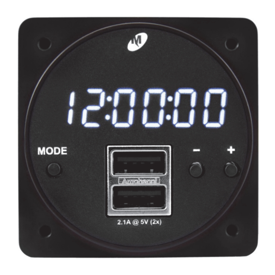
SECTION 1 GENERAL DESCRIPTION INTRODUCTION The MD93 series, part number 6420093-( ) is a digital clock / chronometer with a Dedicated Charging Port (DCP) for USB devices (specifically 2 USB charging ports) fitting into a standard 2 ¼” avionics panel cutout. -
Page 7: Qualifications
QUALIFICATIONS Certification: FAA TSO-C71 EASA ETSO-C71 Environmental Qualification: RTCA DO-160G Environmental Category F1S2BB[(RCC1)(UG)]XXXXXXY[B(XX)]BRXXMXXXAX Table 1 Qualifications UNIT ARCHITECTURE The unit is comprised of two primary building blocks, a USB charger and digital clock. 10-32 VDC input power is regulated, 5 VDC via DC-DC converter used to power the USB charger and all clock/chronometer functions. -
Page 8: Physical Attributes
1.5.3 Physical Attributes Weight: 0.25 pounds Dimensions : 2.385 inches wide x 2.385 inches high x 1.15 inches deep (not including connector) Charging Ports Type: USB Standard-A Clock Digits: 0.360” H x 0.138” W Connector Kit: MCIA P/N 9018178 Mounting: Rear Panel Mount Table 4 Physical Attributes... -
Page 9: Pre-Installation
SECTION 2 PRE-INSTALLATION COOLING The MD93 will become warm when in use; however no external cooling is required. This is normal and within operational parameters. No special mounting considerations are required, although mounting to a metal surface can help dissipate any heat generated and extend the life of the product. EQUIPMENT LOCATION The MD93 Digital Clock / Dual USB Charging Port is designed for a circular rear panel mount configuration, allowing for installation in a cockpit or cabin. -
Page 10: Installation
SECTION 3 INSTALLATION GENERAL This section contains interconnect diagrams, mounting dimensions and other information pertaining to the installation of the MD93 Digital Clock / Dual USB Charging Port. After installation of cabling and before installation of the equipment, ensure that power and ground are applied to the proper pins specified in Section 3.4.2, Pin Assignment Information. -
Page 11: Cable Harness
CABLE HARNESS Construct the cable harness following the instructions outlined below and per Tables 4 and 5. Refer to Section 2: Pre-Installation Considerations for routing precautions. 3.4.1 Wire Gauge Selection Use of PTFE, ETFE, TFE, Teflon or Tefzel insulated wire is recommended for aircraft use. The wire harness should utilize 20-24 AWG stranded wire. -
Page 12: Installation
INSTALLATION The MD93 is rear mounted using a standard 2 ¼” panel cutout. Prepare the panel cutout as shown in Figure 3 below. Prior to installing the unit, the display dimming should be adjusted according to section 3.5.1, Dimming Functions. Mount the MD93 with #6-32 flat head screws (provided with installation kit). NOTE: The maximum screw length used to mount the unit is 9/32”... -
Page 13: Usb Charger Operation
SECTION 4 USB CHARGER OPERATION DESCRIPTION The MD93 Dual USB Charging Port converts aircraft DC input voltage within the range specified to a 5V DC output. This output power is applied to a dual USB-A connector in accordance with the USB Implementers Forum’s Dedicated Charging Port Compliance Plan. -
Page 14: Section 5 Clock / Chronometer Operation
SECTION 5 CLOCK / CHRONOMETER OPERATION DESCRIPTION The clock/chronometer portion of the MD93 has four modes of operation, including local time, universal time, flight timer, elapsed and countdown timers. Specific operation instructions are covered in Section 5.3 (Operational Modes). CONSTRUCTION The clock has six digits that are 0.360”... -
Page 15: Local Time Operation / Setting
5.3.1 Local Time Operation / Setting When power is applied to the MD93, the system defaults to local time mode (there is no indication or annunciation showing “LOCAL” time). To set time and preferences (e.g. 12/24 hour, display or hide seconds) refer to Figure 6. Note: As minutes and seconds can also be set in universal time mode, it is not necessary to set minutes or seconds when setting local time (refer to universal time operation/setting). -
Page 16: Universal Time Operation / Setting
5.3.2 Universal Time Operation / Setting When operational mode is changed to universal time, UTC will be backlit (refer to Figure 7). To set UTC time, refer to Figure 8 - Setting Universal Time. Setting minutes and seconds in UTC time also sets minutes and seconds for local time. -
Page 17: Flight Timer
5.3.3 Flight Timer When operational mode is changed to flight timer, FLIGHT will be backlit (refer to Figure 9). In order for the flight timer to be active, a ground or aircraft power signal must be supplied to pin 4 of the connector. -
Page 18: Timer
5.3.4 Timer When operational mode is changed to the timer function, TIMER will be backlit (refer to Figure 11). The timer function can be operated as either an elapsed timer (stopwatch) or countdown timer, where a specific countdown time can be set. Upon power up, the MD93 remembers countdown timer setting and, when in timer mode, will default to the last mode (elapsed or countdown). -
Page 19: Display Test Mode
If 00:00:00 is displayed, TIMER is in elapsed (stopwatch) mode. If value other than all zeroes (e.g. 00:02:00) is displayed, then TIMER Display TIMER is in countdown mode. Pressing the + button will start and stop the timer operation (either elapsed or countdown). Pressing the – button will reset the timer only if it is stopped. Press &Hold MODE for 2 sec Displays current mode, UP (for elapsed timer) or dn (countdown Select timer) in seconds location. Pressing either – or + buttons toggles between UP and dn timer modes. Press MODE If UP is selected If dn is selected Countdown time is displayed with hours flashing. Pressing the ‐ Timer HOURS Set /+ buttons decrements/increments hours. Press MODE Countdown time is displayed with minutes flashing. Pressing Timer MINUTES Set the ‐/+ buttons decrements/increments minutes. Press MODE Countdown time is displayed with seconds flashing. Pressing Timer SECONDS Set the ‐/+ buttons decrements/increments seconds. Press MODE Figure 12 Elapsed Timer Operation 5.3.5 Display Test Mode To test the MD93 display, press and hold both +/- buttons for 2 seconds. - Page 20 SECTION 6 CONFORMANCE INSTRUCTIONS FOR CONTINUED AIRWORTHINESS No periodic scheduled maintenance or calibration is necessary for continued airworthiness of the MD93 Digital Clock / Dual USB Charging Port. If the unit fails to perform to specifications, the unit must be removed and serviced by Mid-Continent Instruments and Avionics or their authorized designee.
Need help?
Do you have a question about the MD93H and is the answer not in the manual?
Questions and answers