Advertisement
Quick Links
Introduction
TPS-PI-1P1 is an IEEE 802.3at compatible high end remote Power Injector (PI) unit providing
power to a remote Powered Device (PD) e.g. TPS transmitter or receiver. The TPS-PI-1P1
placed in the TPS transmission chain, anywhere between the transmitter and the receiver
unit via the CATx* cable is able to power a TPS device. The incoming data stays untouched,
but a 48V DC remote power is added to the signal by this PI.
* CAT7 AWG 23 SFTP cable is always recommended.
Info: Remote powering of the 95 series HDMI-TPS and DVI-HDCP-TPS devices is not available
by the TPS-PI-1P1 power injector.
Info: Comparing to the details of the powered device's extension distance chart the usage of
the TPS-PI-1P1 may cause approximately 20% distance decrease depending on the
powering mode (local or remote) and cable quality.
Typical application
PI is used for only remote powering
PI supplies both devices with power
This unit provides a uni-directional remote power only, but thanks to the 12V DC local output
option the other device (e.g. HDMI-TPS-RX95) can be powered with the TPS-PI-1P1 if they
are placed close to each other. Powering of the injector itself is provided by its own included
power adaptor.
www.lightware.eu
For technical support contact support@lightware.eu
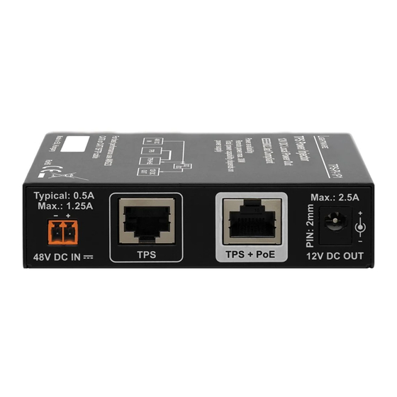
Front and rear view
Status LEDs
1
TPS port (not powered)
48V DC IN
4
Installation
1. Turn off (disconnect) all units, even the video, audio or data devices. Make sure there are no
powered units during the installation.
2. Connect the TPS device to be remote powered (e.g. UMX-TPS-TX140) to the TPS+PoE
connector (2) of the TPS-PI-1P1 Power Injector with a CATx cable.
2
3. Connect the TPS device to be local powered (e.g. HDMI-TPS-RX95) to the TPS connector 3)
of the TPS-PI-1P1 Power Injector with a CATx cable.
4. Connect the desired video, audio and data devices (e.g. Blu-ray players, amplifiers, Ethernet
switch, RS-232 controller, IR transmitter) to the TPS units. Please read the manuals of all
devices to get help during the installation process.
5. Turn on the devices according to the following sequence:
5a. The Power Injector with connecting the 48V DC adaptor to the 48 DC IN connector.
The remote device e.g. UMX-TPS-TX140 gets power immediately.
5b. The local powered device
▪ with connecting its adaptor or
▪ with connecting the supplied patch cable* to the 12V DC OUT (5) of the Power Injector.
5c. Turn on the other devices with methods which are mentioned in theirs user's manuals.
* CAB-12V-U16U (Part No: 13730013)
Info: The maximum distance of the TPS units will not expand by using TPS-PI-1P1.
Warning! Always use the supplied power adaptors. Warranty void if damage occurs due to use
of a different power source.
TPS-PI-1P1
Quick Start Guide
TPS port (powered)
3
2
12V DC OUT
5
5
Document revision: v1.0
3
4
Advertisement

Summary of Contents for Lightware TPS-PI-1P1
- Page 1 Quick Start Guide Introduction Front and rear view TPS-PI-1P1 is an IEEE 802.3at compatible high end remote Power Injector (PI) unit providing Status LEDs power to a remote Powered Device (PD) e.g. TPS transmitter or receiver. The TPS-PI-1P1 placed in the TPS transmission chain, anywhere between the transmitter and the receiver unit via the CATx* cable is able to power a TPS device.
- Page 2 Quick Start Guide Status LEDs The power scheme TPS-PI-1P1 has four front panel LED indicators for monitoring of the operation and troubleshooting. POWER OVERLOAD: [Red] ▪ ON: The delivered power of the wall adaptor exceeds 75% of the maximum value.
Need help?
Do you have a question about the TPS-PI-1P1 and is the answer not in the manual?
Questions and answers