Table of Contents
Advertisement
Chapter 9
In this chapter, learn about the control keys and keypad indications. The main menu maps are
shown here, but for details of sub-menus refer to Chapter 10.
♦
Introduction
♦
6511 - Common Bus Supply
♦
6901 - Common Bus Supply
890CS Common Bus Supply - Frames B & D; 890CD Common Bus Drive and 890SD Standalone Drive - Frames B, C & D
The Keypad
♦
6511 - Common Bus/Standalone Drive
♦
6901 - Common Bus/Standalone Drive
♦
Remote Mounting the Keypad
9-1
The Keypad
Advertisement
Table of Contents

Related Manuals for Parker 6901

Summary of Contents for Parker 6901
- Page 1 Introduction 6511 - Common Bus/Standalone Drive ♦ ♦ 6511 - Common Bus Supply 6901 - Common Bus/Standalone Drive ♦ ♦ 6901 - Common Bus Supply Remote Mounting the Keypad 890CS Common Bus Supply - Frames B & D; 890CD Common Bus Drive and 890SD Standalone Drive - Frames B, C & D...
- Page 2 You can also use a remote mounted 6901 Keypad. Both the 6511 and 6901 Keypad can be mounted up to 3 metres away from the 890 using the optional panel mounting kit with connecting lead: refer to "Remote Mounting the Keypad", page 9-56.
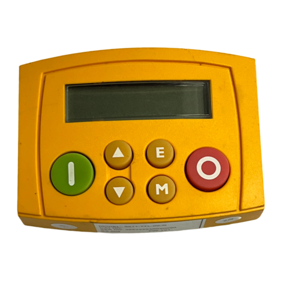
- Page 3 The Keypad 6511 Keypad 890CS Common Bus Supply The 6511 Keypad (Man-Machine Interface, MMI) provides for local control (power-up/power-down), and also monitoring of the five diagnostics provided on the display. To display the Software Version: Press and hold to display software version. To display the Line Voltage Rating: Press and hold to display software version.
- Page 4 The Keypad Control Key Definitions Operation Description Navigation – Hold to display the Welcome screen Escape Trip Message – Clear Trip or Error message from display Bypasses the time-out from the Welcome screen to display the Diagnostics Menu menu. Increment Move up through the Diagnostics menu Decrement Move down through the Diagnostics menu Local Mode...
-
Page 5: Display Indications
The Keypad Display Indications when displaying an Alarm code Displays the units for the value: a negative parameter value for current in Amps for voltage in Volts, for percentage for frequency in Hertz Rrotating = DC link charged Indicates the drive is in Local control. Drive is in remote control when not visible. -
Page 6: The Menu System
The Keypad The Menu System The unit will initialise in Remote Mode from factory conditions. The Keypad will display the Output Power (%). This is the first of five diagnostics. Welcome Screen Displays the software version of the unit From the Welcome Screen, the display times-out (alternatively you can press the key) to show the first of 5 diagnostics: time -out... -
Page 7: Drive Status Indications
The Keypad Drive Status Indications The keypad can display the following status information: Display Status Indication and Meaning Possible Cause READY/HEALTHY No alarms present. Remote mode selected Added or removed from the display letter- LOCAL Local Mode selected, healthy, by-letter to indicate entering or leaving no alarms present Local Mode RUN Not possible to change between... - Page 8 The Keypad Selecting Local or Remote Mode The unit can operate in one of two ways: Remote Mode: Remote control using digital inputs Local Mode: Local control using the Keypad Local control keys are inactive when Remote mode is selected. You can change between local and remote mode from any point on the MMI.
- Page 9 The Keypad 6901 Keypad 890CS Common Bus Supply The 6901 Keypad (Man-Machine Interface, MMI) provides for local control (power-up/power-down), and also monitoring of the five diagnostics I I T D C D O T O R provided on the display.
-
Page 10: Control Key Definitions
9-10 The Keypad Control Key Definitions Operation Description Navigation – Hold to display the Welcome screen Escape Trip Message – Clear Trip or Error message from display Bypasses the time-out from the Welcome screen to display the Diagnostics Menu menu Increment Move up through the Diagnostics menu Decrement... - Page 11 9-11 The Keypad Example: To view the INPUT CURRENT diagnostic 1. The display will default to show the OUTPUT POWER (%) diagnostic. OUTPUT POWER 2. Press the key repeatedly to scroll to the INPUT CURRENT (A) diagnostic. INPUT CURRENT 0.0 A Alternatively, press the key just once to cycle through the list.
-
Page 12: Led Indications
9-12 The Keypad LED Indications There are seven LEDs that indicate the status of the drive. Each LED is considered to operate in three different ways: The LEDs are labelled HEALTH, LOCAL (as SEQ and REF), RUN, STOP, FLASH FWD and REV. (FWD and REV are unused). Combinations of these LEDs have the following meanings: HEALTH STOP... - Page 13 9-13 The Keypad The Menu System The unit will initialise in Remote Mode from factory conditions. The Keypad will display the Output Power (%). This is the first of five diagnostics. Welcome Screen Displays the software version of the unit WELCOME SCREEN From the Welcome Screen, the display times-out to show the first of 5 diagnostics:...
- Page 14 E key. Experience will show how to avoid most messages. When using the 6901 keypad, they are displayed in clear, concise language for easy interpretation. Refer to Chapter 11: “Trips and Fault Finding” for trip messages and reasons.
- Page 15 9-15 The Keypad Selecting Local or Remote Mode The unit can operate in one of two ways: Remote Mode: Remote control using digital and analog inputs and outputs Local Mode: Providing local control and monitoring of the drive using the Keypad Local control keys are inactive when Remote Mode is selected.
- Page 16 9-16 The Keypad 6511 Keypad 890CD Common Bus Drive/890SD Standalone Drive The 6511 Keypad (Man-Machine Interface, MMI) provides for local control of the drive, monitoring, and complete access for application programming. To display the Software Version: Press and hold to display software version.
- Page 17 9-17 The Keypad Control Key Definitions Operation Description Navigation - Moves upwards through the list of parameters. Parameter Escape - Increments the value of the displayed parameter. Command Acknowledge - Confirms action when in a command menu. Navigatio n - Moves downwards through the list of parameters. Menu Parameter - Decrements the value of the displayed parameter.
- Page 18 9-18 The Keypad Display Indications when displaying an Alarm code Displays the units for the value: a negative parameter value for current in Amps for voltage in Volts, for percentage for frequency in Hertz for seconds Indicates the Control Mode Indicates the drive is in Remote...
- Page 19 9-19 The Keypad The Menu System The unit will initialise in Remote Mode from factory conditions. The Keypad will display the Operator Menu. Each menu contains parameters. The Menu System Welcome Screen Displays the software version of the unit From the Welcome Screen, the display times-out (alternatively you can press the key) to show the first of 4 menus: time -out...
- Page 20 9-20 The Keypad The Menu System Map The Menu System Press to view parameter value time-out Change value with keys Press to exit parameter Note: this does not save the link configuration. It saves information for MMI parameters. 890CS Common Bus Supply - Frames B & D; 890CD Common Bus Drive and 890SD Standalone Drive - Frames B, C & D...
- Page 21 9-21 The Keypad Drive Status Indications The keypad can display the following status information: Display Status Indication and Meaning Possible Cause READY/HEALTHY No alarms present. Remote mode selected PASSWORD Current password must be Enter password to change the parameter. entered before this parameter may be Refer to page 9-50.
- Page 22 9-22 The Keypad Alert Message Displays A message will be displayed on the Keypad when either: ♦ A requested operation is not allowed ♦ The drive has tripped Most messages are displayed for only a short period, or for as long as an illegal operation is tried, however, trip messages must be acknowledged by pressing the E key.
- Page 23 9-23 The Keypad Selecting Local or Remote Mode The unit can operate in one of two ways: Remote Mode: Remote control using digital and analog inputs and outputs Local Mode: Local control using the Keypad Local control keys are inactive when Remote Mode is selected. You must be at the top of the MMI, showing the software version, before you can change between local and remote modes.
-
Page 24: How To Change A Parameter Value
9-24 The Keypad How To Change a Parameter Value You can change the values of parameters stored in the menus. Refer to Chapter 10 for further information. • View the parameter to be edited and press to display the parameter’s value. •... - Page 25 9-25 The Keypad How to Save the Application The SAVE menu, available in all menu levels, is used to save any changes you make to the Keypad settings. Press the UP key as instructed to save all parameters. Values are stored during power-down. 890CS Common Bus Supply - Frames B &...
-
Page 26: Special Menu Features
9-26 The Keypad Special Menu Features Resetting to Factory Defaults (2-button reset) Power-up the drive whilst holding the keys as shown to Hold down the keys opposite: HOLD return to factory default settings. Power-up the drive, continue This loads default values for all pre-defined parameters. to hold for at least 1 second Then press the key. -
Page 27: Power-Up Key Combinations
9-27 The Keypad Power-up Key Combinations Resetting to Factory Defaults (2-button reset) A special key combination restores to the drive the current product code default parameter values. This feature is only available at power-up as a security measure. Note If the unit is operating on 24V dc only for configuration purposes, the unit will trip on UNDERVOLTAGE (DCLO) as to be expected. -
Page 28: Changing The Product Code (3-Button Reset)
IMPORTANT We recommend Hold down the keys opposite: the menus marked Power-up the drive, continue * above are only to hold for at least 2 seconds used by Parker SSD Drives or for example suitably qualified personnel. Note The LANGUAGE... - Page 29 9-29 The Keypad POWER BOARD (6511 keypad) HOLD CD/SD 230Vac Units: Hold down the keys opposite: PROG Size Model No. Rating Code Power-up the drive, continue Block 2 to hold for at least 2 seconds Frame B 1300B 0.75 HP/0.55kW 131 1550B 1.5 HP/1.1kW 1700B...
- Page 30 Settings will only be updated following a “restore macro” operation. The default is 50Hz (6511 keypad = 0 , 6901 keypad = FALSE). Refer to Appendix D: “Programming” - Frequency Dependent Defaults.
- Page 31 9-31 The Keypad 6901 Keypad 890CD Common Bus Drive/890SD Standalone Drive The 6901 Keypad (Man-Machine Interface, MMI) provides for local control of the drive, monitoring, and complete access for application programming. To display the Software Version: I I T D C D...
-
Page 32: Keys For Programming The Drive
9-32 The Keypad Control Key Definitions Keys for Programming the Drive Navigation - Moves upwards through the list of parameters or menus Parameter - Increments the value of the displayed parameter. Command Acknowledge - Confirms action when in a command menu. Navigatio DOWN n - Moves downwards through the list of parameters or menus... -
Page 33: Keys For Operating The Drive Locally
9-33 The Keypad Keys for Operating the Drive Locally Control FORWARD/ - Changes the direction of motor rotation. Only operates when the drive REVERSE is in Local Speed Control mode. Control - Runs the motor at a speed determined by the JOG SETPOINT parameter. - Page 34 9-34 The Keypad The L/R Key The L/R key (LOCAL/REMOTE) toggles between Remote and Local Mode. In doing so, the view of the SETPOINT parameter in the OPERATOR menu toggles between SETPOINT (LOCAL) and SETPOINT (REMOTE). The default is for the SETPOINT (REMOTE) parameter to be displayed. Note A different naming convention is applied in the OPERATOR menu for these parameters when displayed as the first parameter entry:...
- Page 35 9-35 The Keypad The PROG Key The PROG key toggles between the OPERATOR menu and any other menu, remembering and returning to previous positions in each menu. As you press the PROG key, the title of the menu you are about to enter is displayed, i.e.
- Page 36 9-36 The Keypad LED Indications There are seven LEDs that indicate the status of the drive. Each LED is considered to operate in three different ways: The LEDs are labelled HEALTH, LOCAL (as SEQ and REF), RUN, STOP, FLASH FWD and REV. Combinations of these LEDs have the following meanings: HEALTH STOP Drive State...
- Page 37 9-37 The Keypad Forward / Reverse State Requested direction and actual direction are forward Requested direction and actual direction are reverse Requested direction is forward but actual direction is reverse Requested direction is reverse but actual direction is forward LOCAL LOCAL Local / Remote Mode Start/Stop (Seq) and Speed Control (Ref) are controlled from the terminals...
- Page 38 9-38 The Keypad The Menu System The unit will initialise in Remote Mode from factory conditions. The Keypad will display the Operator Menu. Each menu contains parameters. Welcome Screen Displays the software version of the unit WELCOME SCREEN From the Welcome Screen, the display times-out (alternatively you can press the key) to show the first of 4 menus: A customised view of selected parameters...
- Page 39 9-39 The Keypad The Menu System Map WELCOME SCREEN MOTOR CONTROL AUTOTUNE OPERATOR CURRENT LIMIT menu at level 1 DYNAMIC BRAKING DIAGNOSTICS ENCODER menu at level 1 ENERGY METER FEEDBACKS QUICK SETUP menu at level 1 FLUXING FLYCATCHING SETUP CANOPEN INERTIA COMP menu at level 1 COMMUNICATIONS...
- Page 40 9-40 The Keypad The Menu System Map continued PHASE CONTROL FIREWIRE REF MOVE TO MASTER PHASE MOVE PHASE MOVE ABS PHASE OFFSET V MASTER SIMLATR SEQ & REF AUTO RESTART COMMS CONTROL REFERENCE JOG REFERENCE RAMP REFERENCE STOP SEQUENCING LOGIC TRIPS I/O TRIPS OVER SPEED TRIP...
-
Page 41: Navigating The Menu System
9-41 The Keypad Navigating the Menu System On power-up, the Keypad defaults into the OPERATOR menu, scroll timing out from the Welcome screen. You can skip the timeout by pressing the key immediately after power-up which will take you directly to the OPERATOR menu. exit to previous next menu... - Page 42 9-42 The Keypad Alert Message Displays A message will be displayed on the Keypad when either: • A requested operation is not allowed: * KEY INACTIVE * The top line details the illegal operation, while the bottom line gives the REMOTE SEQ reason or cause.
- Page 43 9-43 The Keypad Selecting Local or Remote Mode The unit can operate in one of two ways: Remote Mode: Remote control using digital and analog inputs and outputs Local Mode: Providing local control and monitoring of the drive using the Keypad Local control keys are inactive when Remote Mode is selected.
- Page 44 9-44 The Keypad How To Change a Parameter Value You can change the values of parameters stored in the OPERATOR, QUICK SETUP and SETUP menus. Refer to Chapter 10 for further information. • View the parameter to be edited and press to display the parameter’s value.
- Page 45 9-45 The Keypad How to Save the Application The SAVE menu, available in all menu levels, is used to save any changes you make to the Keypad settings. Press the UP key as instructed to save all parameters. Values are stored during power-down. SAVE CONFIG SAVE CONFIG `UP` TO CONFIRM...
- Page 46 9-46 The Keypad Special Menu Features Selecting the Menu Level MMI Menu Map For ease of operation there are three `viewing levels’ for the Keypad. QUICK SETUP The setting for the VIEW LEVEL parameter decides how much of the menu system will be displayed. The choice of menu for each has been VIEW LEVEL designed around a type of user, hence we have the Operator, Basic and Advanced viewing levels.
-
Page 47: Quick Save Feature
9-47 The Keypad Quick Save Feature From anywhere in the menu system, hold down the PROG key for approximately 3 seconds to move quickly to the SAVE CONFIG menu. You can save your application and return conveniently to your original display. 890CS Common Bus Supply - Frames B &... - Page 48 9-48 The Keypad DIAGNOSTICS for example menu at level 1 PROG HOLD SAVE CONFIG menu at level 2 SAVE CONFIG for example SAVE CONFIG "UP" TO CONFIRM SAVE CONFIG menu at level 2 DISPLAYS OPERATOR MENU PROG (NORMAL ACTION OF PROG KEY) SETPOINT (REMOTE) 0.0 % for example...
-
Page 49: Quick Tag Information
9-49 The Keypad Quick Tag Information With a parameter displayed, hold down the M key for approximately 3 seconds to display the parameter’s tag number (a message may be displayed during this time). RAMP TIME 100.00 % HOLD FOR 3 SECONDS RAMP TIME PREF RAMP TIME... - Page 50 9-50 The Keypad Password Protection (6901 keypad) MMI Menu Map When activated, the password prevents unauthorised parameter modification by making all parameters “read-only”. If you attempt to SETUP modify a password protected parameter, you will be prompted for the password.
- Page 51 9-51 The Keypad To De-activate Password Protection If you try to change the value of a parameter with password protection activated, the PASSWORD screen is displayed for you to enter the current password. If you enter the password correctly password protection is temporarily de-activated.
- Page 52 If the unit is operating on 24V dc only for configuration purposes, the unit will trip on UNDERVOLTAGE (DCLO) as to be expected. Press the "E" key to clear the trip message when it appears. 6901 Keypad Combination Hold down the keys opposite: HOLD...
- Page 53 EXIT TO BOOT below Select from the expanded SYSTEM menu IMPORTANT We recommend the menus marked * above are only used by Parker SSD Drives or suitably qualified personnel. Note The LANGUAGE menu currently contains selection for ENGLISH only. 890CS Common Bus Supply - Frames B & D; 890CD Common Bus Drive and 890SD Standalone Drive - Frames B, C & D...
- Page 54 9-54 The Keypad POWER BOARD (6901 keypad) HOLD Hold down the keys opposite: PROG Power-up the drive, continue to hold for at least 2 seconds POWER DATA CORRUPT Config mode is selected, indicated by all LEDs flashing POWER BOARD ????kW...
- Page 55 Settings will only be updated following a “restore macro” operation. The default is 50Hz (6511 keypad = 0 , 6901 keypad = FALSE). Refer to Appendix D: “Programming” - Frequency Dependent Defaults.
-
Page 56: Remote Mounting The Keypad
Remote Mounting the Keypad Fitting the Remote 6901 Keypad The 6052 Mounting Kit is required to remote-mount a 6901 Keypad. An enclosure rating of IP54 is achieved for the remote Keypad when correctly mounted using the 6052 Mounting Kit. 6052 Mounting Kit Parts for the Remote Keypad Tools Required No. -
Page 57: Assembly Procedure
The Keypad Assembly Procedure Template To Keypad Port Figure 9.1 Mounting Dimensions for the Remote-Mounted 6901 Keypad 890CS Common Bus Supply - Frames B & D; 890CD Common Bus Drive and 890SD Standalone Drive - Frames B, C & D... - Page 58 9-58 The Keypad Fitting the Remote 6511 Keypad You can remote-mount the keypad using a standard P3 lead, SSD Part Number CM057375U300, to connect the keypad to the drive. Two self-tapping screws are provided with the keypad. Remove the protective film from the gasket. An enclosure rating of IP54 is achieved for the remote keypad when correctly mounted.
- Page 59 9-59 The Keypad Assembly Procedure 72mm ± Template ± ± 54mm ± ± 15.5 Cut-out 26mm ± Figure 9.2 Mounting Dimensions for the Remote-Mounted 6511 Keypad 890CS Common Bus Supply - Frames B & D; 890CD Common Bus Drive and 890SD Standalone Drive - Frames B, C & D...
- Page 60 890CS Common Bus Supply - Frames B & D; 890CD Common Bus Drive and 890SD Standalone Drive - Frames B, C & D...
Need help?
Do you have a question about the 6901 and is the answer not in the manual?
Questions and answers