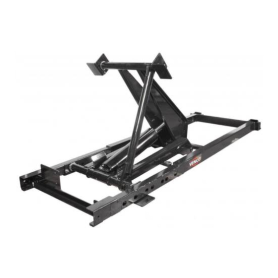
Summary of Contents for VENCO VC-416 ES
- Page 3 TABLE OF CONTENTS BOOKMARKS THUMBNAILS VP / VC - 6D MANUAL PAGE DESCRIPTION REF. NO. GENERAL INFORMATION ............6246 PREPARATION - MOUNTING HOIST ........6241 UPPER NEST & REAR HINGES ..........6248 HOIST FRAME ON CHASSIS ..........6242 LONGITUDINAL SUPPORTS - OPTION ........6244 HYDRAULICS .................
- Page 4 VP/VC-6D HOIST SPECIFICATIONS OVERVIEW VP - PICK-UP Power Source: VC - CONTRACTOR ES - Electric Single Acting 6 - *6000 lbs. CAPACITY ED - Electric Double Acting Designed for: '94 - Current Dodge 1/2 & 3/4 ton pickup trucks and club cabs NOTE: For optional longitudinal body supports - add 30 lbs.
- Page 5 VP-6D DODGE PICKUP HOIST INSTALLATION INSTRUCTIONS Remove pick-up bumper and pickup body and remove spare tire winch extension at right of license plate bracket. Keep the extension and bracket to be reinstalled later. Disconnect tail lights or any other electrical items attached to the bed (pickup body). Save the bed bolts. 2B.
- Page 6 TITLE DATE SECTION INSTALLATION DRAWING 7-6-98A H200 MANUFACTURING, INC. SUPERCEDES 6248 VP/VC-6D 1-31-95...
- Page 7 5&6. Longitudinal Supports (optional) & Plastic Pads: - See instructions on page 6244 Hoist Mainframe: The Hoist Mainframe is offset 2-1/2 inches toward the curb side (right side). Put 3/8"-16 x 3" bolts with flat washer up through the inside of the chassis frame rails on each side of the crossmember and up through the 2 inch square tube - 7/16"...
- Page 8 TITLE DATE SECTION INSTALLATION DRAWING 7-6-98 H200 MANUFACTURING, INC. SUPERCEDES 6244 VP/VC-6D 1-30-95...
- Page 9 Installing Hydraulics: Important - Be sure to blow dirt and other material out of the hose(s) with compressed air to prevent the hydraulic system from being contaminated. ED (Electric Double Acting) Power Unit: See Dwg. 6096 (Bi-rotational power unit) 1. Install the short hydraulic hose to the full/base end of the cylinder. Connect the long hydraulic hose to the rod end of the cylinder.
- Page 15 STEP 6 - Refill the reservoir with the remaining fluid required. STEP 7 - Attach hose to rod end of cylinder on the 416, 516, 520 ES models. Example: VC-416 ES/ED Hoist Step 2 - Add 3.5 qts. Step 3 - Add 2.0 qts.
- Page 17 10. Dash Control Switch Installation: See Dwg. 40124 - Install dash mounting plate under the dash in a convenient location for operator control. Use the #12 pan head slotted screws, 1/2" long, furnished in kit. - Install switch extension onto toggle switch. - Connect center post of switch to the 20 amp in-line fuse.
- Page 19 11. Upper Nest Pivot Assemblies: Be sure the short Upper Pivot Assembly is on the left side and not hitting the Fuel Tank. Be sure that the vertical flange on the Upper Pivot Assembly is toward the cab. See Figure 7D on page 6242 and Figure 11 below.
- Page 20 13A. Attaching Upper Nest Pivots to Upper Nest: See Figure 13A Be sure the flanges on the Upper Pivot are positioned as specified in Step 11, with the vertical flange toward the cab. Power the hoist upward so the Upper Pivots make contact with the Upper Nest.
- Page 21 14. Fuel Filler Tube & Support: Decide where the fill will be (there are two options): 1. Similar to original location but shorter - to clear the bottom of the pickup body when the body is raised. The pickup body will have to be raised to fill tank. Or as shown in figure 14 above, Option 2, positioned so the fuel fill tube is under the Left Wheel House above the left rear tire.
- Page 24 These decals are for the safety of anyone who may operate this unit and is intended to protect all parties from potential liability. VENCO CONTRACTOR HOIST - MODEL VC-6D The installation of a VC-6D hoist is identical to the VP-6R hoist with the following exceptions: The rear pivot angle is welded to the truck frame.
- Page 25 VC-6D DODGE CONTRACTOR HOIST If a distance of more than 38" is exceeded between the centers of the rear axle and rear hinge assembly, additional reinforcement of the truck frame will be required. Mark the location for the rear hinge. This location should be immediately behind a truck crossmember.
- Page 27 VP/VC-6D REPLACEMENT PARTS LIST ITEM VP-6D VC-6D DESCRIPTION 6203 (2) 40238 UPPER NEST / CONTRACTOR ASSEMBLY 6204 UPPER NEST PIVOT ASSEMBLY 6205 UPPER HINGE ASSY. / UPPER REAR HINGE (R & L) 6206 6206 BASE MOUNTING PLATE ASSEMBLY 6226 LONGITUDINAL BODY SUPPORT - LEFT, OPTION 6227 LONGITUDINAL BODY SUPPORT - RIGHT, OPTION 6207...
- Page 28 40058-2 SINGLE-ACTING HYDRAULIC POWER UNIT SERVICE PARTS LIST DATE SECTION TITLE SERVICE PARTS LIST 12-3-98A H400 MANUFACTURING, INC. SUPERCEDES 40058-2 VP/VC 6, VC 416/516/520 5-14-98...
- Page 29 TITLE DATE SECTION SERVICE PARTS LIST 12-10-98B H400 MANUFACTURING, INC. SUPERCEDES 6097 VP/VC-6 SERIES 5-15-98A...
- Page 30 6425 ED POWER UNIT REPLACEMENT PARTS REPLACEMENT PARTS LIST REF 6487 TITLE DATE SECTION REPL. PARTS DWG 6-2-00A MANUFACTURING, INC. SUPERCEDES 6486 6425 ED POWER UNIT 2-11-00...
- Page 32 TITLE DATE SECTION REPL. PARTS LIST 5-30-00 MANUFACTURING, INC. SUPERCEDES 6508 6426 ES POWER UNIT...


Need help?
Do you have a question about the VC-416 ES and is the answer not in the manual?
Questions and answers